background image


Document: Service Manual 
Description: Treadmill 

Model: M6 AC 

Page: 6 of 20 


1.3.


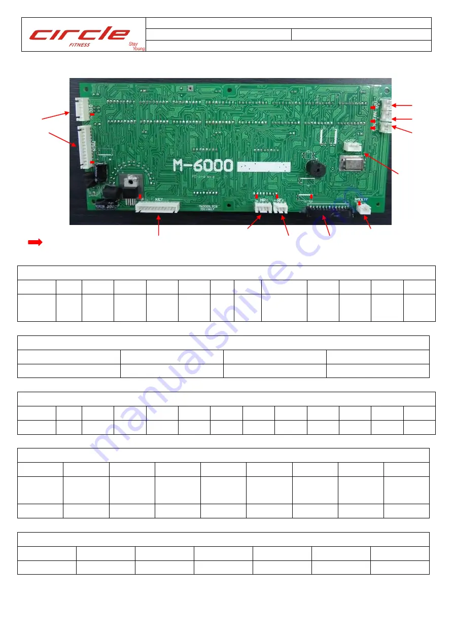
Console PCB: 


Definition of JK1(MAIN / Console wire) Connector 

PIN 

10 

11 

12 

Define 

+5V  ADC 

GND  Down 

Up 

RP

M   

+5V 

Motor 

EN 

Slow 

Fast 

GND  +12V 


Definition of J1(ISP / Program Updater) Connector 

PIN 

Define 

+5V 

TXD 

GND 


Definition of J2(KEY) Connector 

PIN 

10 

11 

12 

Define 

COM 

SLOW 

FAST 

DOWN 

UP 

PROGRAM 

ENTER 

STOP 

START 


Definition of J3(Membrane key) Connector 

PIN 

10 

(speed)


8


(speed)


6


(speed)


4


(speed)


6


(Incline)


4


(Incline)


2


(Incline)


8


(Incline)


10 


Display 

FAN 


Definition of J7(OTC) Connector 

PIN 

Define 

VCC 

UP 

DOWN 

FAST 

SLOW 

GND 


J2 (Key board) 

JK5 

(HP) 

JK4 

(RF) 

JK2 

(SAFETY) 

JK9 
JK8 
JK7 

J7 
JK1 

J1 

(ISP) 

: PIN 1 

J3 

Summary of Contents for M6 AC

Page 1: ......

Page 2: ...11 4 Engineering Mode 4 1 Engineering Mode 1 Basic Settings Page 12 4 2 Engineering Mode 2 Used Information Management Page 12 4 3 Engineering Mode 3 Erase the Custom Settings to Default Value Page 12 4 4 Engineering Mode 4 Real Time Speed Incline Parameter Page 12 4 5 Engineering Mode 5 Default Age Value Of Quick Start Page 13 4 6 Engineering Mode 6 Incline Test Settings Page 13 4 7 Engineering M...

Page 3: ...Document Service Manual Description Treadmill Model M6 AC Page 3 of 20 3 1 Information For Components System 1 1 System Wiring Diagram ...

Page 4: ...r PIN 1 2 3 Define 5V ADC GND Description of pilot lamps LED1 RED Motor driver output pilot lamp Red Lights up normally LED1 Green System power LED lights up normally when power on TR6 Incline motor up pilot lamp Green Lights up while incline motor go up TR5 Incline motor down pilot lamp Yellow Lights up while incline motor go down Definition of Incline Control Connector PIN 1 2 3 4 5 Define DOWN ...

Page 5: ... 2 2 1 Inverter modification 1 2 2 2 DB Fixation 1 2 2 3 Connection of DB to inverter Appearance of Dynamic Brake Short circuit the CON1 where on the inverter Fix on the main frame Screws 110V system DB wire N connects to the negative pole of bridge rectifier DB wire P connect to CON1 on inverter 220V system DB wire N connects to the negative pole of bridge rectifier DB wire P connect to CON1 on i...

Page 6: ...r Connector PIN 1 2 3 Define 5V TXD GND Definition of J2 KEY Connector PIN 1 2 3 4 5 6 7 8 9 10 11 12 Define X COM X SLOW FAST DOWN UP PROGRAM ENTER STOP START X Definition of J3 Membrane key Connector PIN 2 3 4 5 6 7 8 9 1 10 speed 8 speed 6 speed 4 speed 6 Incline 4 Incline 2 Incline 8 Incline 10 Display FAN Definition of J7 OTC Connector PIN 1 2 3 4 5 6 Define VCC UP DOWN FAST SLOW GND J2 Key b...

Page 7: ...JK2 SAFET Connector PIN 1 2 Define 5V Control Definition of JK7 8 FAN Connector PIN 1 2 Define PWM GND Definition of JK9 MP3 Connector PIN 1 2 Define 12V GND Definition of JK4 RF Connector PIN 1 2 3 Define VCC GND Output Definition of JK5 HP Connector PIN 1 2 3 4 Define VCC GND Output 12V ...

Page 8: ...ire not well or wire damaged while assemble Determine Solution Show SPEED ERROR Turn OFF the AC power and wait 10 seconds then turn ON the AC power Press START Do the running belt moved Speed Feedback system program if happen regularly replace the speed sensor No Open the motor cover then turn ON the AC power press START to begin and check the pilot lamp on motor driver Did the LED1 lights up Moto...

Page 9: ...cline parameter Did the incline moved while press incline up or down key No Yes Did the UP or DOWN LED on inverter lights up while press incline up or down key Replace console PCB No Check sure face temperature of incline motor is it hot Yes Wait for cool down then back to execute from step A If not work after cool down to execute from step B No To strip the incline motor down then check the incli...

Page 10: ...ole cover and reference to page 6 to measure the PIN 11 12 voltage of upper console wire does it have 12V power Yes Replace console wire Replace console PCB Yes No Were all keys lose function Turn off the power and wait for 10 seconds then turn on Are the keys become normal Yes Cause by external noise need to find out and check again in the further Open the console and reference to page 6 to short...

Page 11: ...motor cover then press increase or decrease speed key belt speed can be more fast or slow No Yes Replace speed sensor No Use keypad to modify the inverter parameter F_001 to 1 F_002 to 3 reference to 6 keypad usage then press RUN does the running belt move To check the console wire it shall not be crush injuries or breakage refer to photos in 3 1 No Replace inverter Yes Replace console ...

Page 12: ... 7MPH press Enter to confirm and to next setting 4 1 5 Max speed setting Message window show MAX SPEED 20 0 press Speed Fast or Speed Slow to set the min speed setting range 8 25KPH 5 15 5MPH press Enter to confirm and back to idle mode 4 2 Engineering Mode 2 Used Information Management Pull out the safety key press Quick Start Speed Slow then put back the safety key to enter mode 4 2 1 Time windo...

Page 13: ... adjust the incline motor position the parameter will be change according to incline position press Start wait for a beep sound to save the max incline parameter message window show MAX AD OOO XXX the OOO and XXX value will the same after saving press Enter to confirm and to next setting default 195 4 6 4 Min incline parameter message window show MIN AD OOO XXX OOO old setting memory value XXX rea...

Page 14: ...site Driver document cursor on file 0E6A030D_8051ISPICP_v3 00 then click mouse right side and select Install I 5 2 Programmer Update 5 2 1 Connect the programmer to PC USB port the LED2 LED3 on programmer will be light up 5 2 2 Execute the programmer update PC site software in the un zipped document 5 2 3 Settings 5 2 3 1 Programmer Type select ISP 5 2 3 2 MCU Part No select 82 Series MG82FL E 564...

Page 15: ...5 5 2 4 Load burning code and update programmer click Load File Select AP Code then press ok Select and open the burning code click Update Programmer Max Count 0 press OK update success 5 3 Product Update 5 3 1 Turn off the power then open the console see as below LED3 flash ...

Page 16: ...of 20 16 5 3 2 Connect the programmer to J1 ISP of console PCB 5 3 3 Turn ON the power then to press the update button to update the program 5 3 4 Please remove the programmer and reboot the system to finish the update reset power Update button LED1 Flash Done LED1off ...

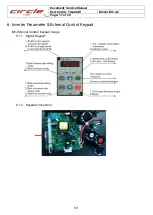
Page 17: ...Document Service Manual Description Treadmill Model M6 AC Page 17 of 20 17 6 Inverter Parameter External Control Keypad 6 1 External Control Keypad Usage 6 1 1 Digital Keypad 6 1 2 Keypad connection ...

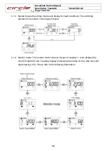
Page 18: ...splay for fault conditions The switching operations are shown in the diagram below 6 1 4 Monitor mode The monitor mode contains 8 types of displays 1 main display the most left digit off and 7 auxiliary displays indicating the status of drive the most left digit showing 2 8 Please refer to the following illustrations ...

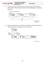
Page 19: ...mode In the function code setting mode total 135 function codes F_000 F_134 can be input to the drive and the setting diagram is shown in the figure below 6 1 6 Parameter setting mode In the parameter setting mode the range setting is defined in function code and the setting diagram is shown in the below ...

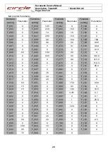
Page 20: ...0 F_044 0 F_077 0 0 F_114 215 0 F_012 0 F_045 0 F_078 0 F_115 110 3 F_013 0 F_046 1 F_079 0 F_116 85 0 F_014 0 F_047 0 F_080 0 F_117 0 F_015 0 F_048 7 8 F_081 6 F_118 0 F_016 0 F_049 3 4 F_082 1 F_119 9 F_017 0 F_050 2 0 F_083 0 F_120 0 F_018 60 F_051 0 F_088 150 F_121 0 00 F_019 15 F_052 0 F_089 0 5 F_122 0 F_020 15 F_053 0 F_090 100 F_123 10 5 F_021 0 F_054 0 F_091 1LE1 F_124 0 7 F_022 0 F_055 0...

Reviews: