


14
1)
Main Panel Switch On/Off:
When this switch is on, the control panel is on. This means
the two controllers which controls the burner are on along with the voltmeter.
2)
Volt Meter:
This voltmeter displays the voltage of the battery while the control panel is
on.
3)
Diesel Burner LED (Yellow):
This LED indicates that the Diesel Burner is on.
4)
Heat Transfer Oil LED (Green):
This LED indicates that the Heat Transfer Oil has
reached the preset temperature. This indicates that you can turn the agitator on.
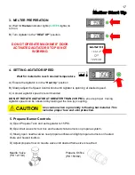
5)
Oil Temperature Controller:
The controller for your CIMLINE ME3 melter has been
factory set to run ISO Grade 68 heat transfer oil.
6)
Material LED (Green):
This LED indicates that the Material has reached the preset
temperature.
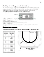
7)
Material Temperature Controller:
The control system on your CIMLINE ME3 melter has
been factory set to run the most common types of materials. See page 17 to override
settings.
8)
Panel Power LED (Green):
This LED indicates that the control panel is on.
Sub Control Panel Controls and Their Functions
Summary of Contents for ME3
Page 15: ...15 Sub Control Panel Controls and Their Functions 1 2 3 4 6 7 8 5 ...
Page 34: ...34 Trailer Wiring Diagram ...
Page 39: ...39 Burner Internal Wiring Diagram ...
Page 43: ...43 Mastic Hydraulic Manifold Components ...
Page 44: ...44 Hydraulic Schematic ...
Page 49: ...49 Miscellaneous Parts 28 29 30 30 ...
Page 51: ......
Page 52: ...52 2601 Niagara Lane Plymouth MN 55447 763 557 1982 800 328 3874 Fax 763 557 1971 ...


