


31
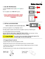
ME3 Maintenance - Tank Burner
Primary Controller:
The Beckett ADC tank burner motor is used to drive the blower and pump. The rotational speed of
the motor is determined by the voltage supplied and the load placed on the motor. Pump pressure
and air settings are the main factors affecting the motor load. The ignition transformer converts
battery DC voltage into a high voltage spark to ignite the fuel. The pump and solenoid valve are used
to control the flow of fuel from the reservoir to the nozzle.
The tank burner has a control circuit to reduce current draw on the charging system by turning the
igniter off after a flame has been established. This circuit controls ignition transformer operation
based on a signal from a light sensing cad cell (electric eye). When light hits the cell the control will
sense a decrease in resistance across the sensor. As long as sufficient light is reaching the cell eye,
the igniter will remain off. If light is removed from the sensor, the igniter will turn on until light is again
sensed by the cad cell.
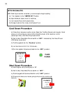
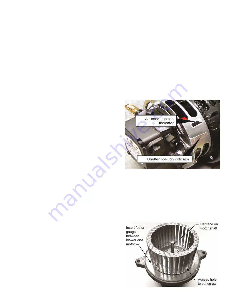
Air Supply Set-up:
The tank burner is set up properly from the factory.
Air Band Position (A) should be set to 1
Shutter Position (B) should be set to 6
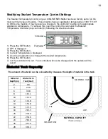
Motor, Blower Wheel and Coupling
Replacement:
See page 48 for the tank burner parts exploded view
A. Before servicing, turn off and/or disconnect all
power to the burner.
B. Disconnect the burner motor wires.
C. Remove the bolts securing the motor to the burner housing.
D. Remove the motor, coupling, and blower wheel.
E. Loosen the set screw on the blower wheel to slide the existing wheel off the shaft.
F. Slide the new blower wheel onto the old shaft and/or slide the old blower wheel onto the new
motor shaft.
G. Place a .030” (1/32” ± 1/64”) feeler gauge between the blower wheel and the motor housing.
H. Slide the blower wheel toward the motor until it contacts the feeler gauge.
I. Rotate the blower wheel until the setscrew is
centered on the flat of the motor shaft. Tighten
the setscrew to secure the wheel.
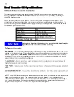
J. Slide the motor coupling on the motor shaft,
then install the motor on the burner housing.
Ensure that the motor coupling fits between the
motor shaft and the pump shaft inside the
housing. Tighten the motor retaining screws.
Reconnect the wires.
(A)
(B)
Summary of Contents for ME3
Page 15: ...15 Sub Control Panel Controls and Their Functions 1 2 3 4 6 7 8 5 ...
Page 34: ...34 Trailer Wiring Diagram ...
Page 39: ...39 Burner Internal Wiring Diagram ...
Page 43: ...43 Mastic Hydraulic Manifold Components ...
Page 44: ...44 Hydraulic Schematic ...
Page 49: ...49 Miscellaneous Parts 28 29 30 30 ...
Page 51: ......
Page 52: ...52 2601 Niagara Lane Plymouth MN 55447 763 557 1982 800 328 3874 Fax 763 557 1971 ...


