


INSTALLATION/SETUP
TRANSMIG 2RT
Manual 0-5196
3-15 INSTALLATION/SETUP
3.17 Changing the Feed Roll
NOTE
Feedrolls often come with a rust prohibitive
coating that needs to be cleaned off before
installation.
A Feedroll consists of two different sized grooves. As
delivered from the factory the drive roll is installed for
0.9mm / 1.2mm.
The stamped marking on the feedroll refers to the groove
furthest from the stamped marking. When mounted, that
will be the groove closest to the motor and the one to
thread.
To ensure proper wire feed, the groove closest to the
motor must match the electrode wire size being used.
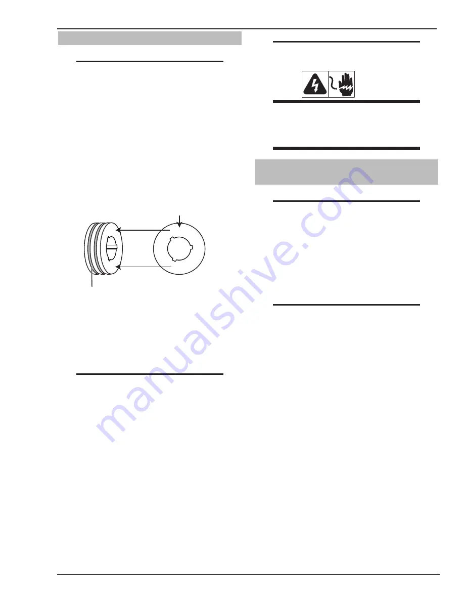
1.2mm (.045”) Groove
Art: A-10345
The size that is visible when
fitting the feedroll is the groove
size in use.
.045
1.2
1.2mm (.045”) Stamping
.045
1.2
Figure 3-14: Feedroll Example
NOTE
All grooved feed rolls have their wire size or
range stamped on the side of the roll. On rolls
with different size grooves, the outer (visible
when installed) stamped wire size indicates
the groove in use.
Refer to feed roll kit in the Appendix for the proper selec-
tion and ordering of feed roll kits. Kit includes drive rolls,
an input wire guide and an output wire guide for a specific
wire type and size.
Feed rolls are removed by twisting the feed roll retainer
cap and aligning the retaining knob splines/tabs with
the drive gear splines. Feedrolls are installed by putting
the feedroll onto the drive gear splines and twisting the
feedroll retainer cap so that the splines/tabs rest against
the face of the feedroll where they will click into place.
NOTE
Installation of all styles of feed rolls for the
Transmig 250i are identical.
WARNING
The welding wire is electrically Hot if it is fed
by depressing MIG Torch switch. Electrode
contact to work piece will cause an arc with
MIG Torch switch depressed.
3.18 Input And Output Wire Guide
Installation
NOTE
0.9mm / 1.2mm feed rolls and guides are
installed from the factory. Other sizes need
to be purchased separately.
Input Wire Guide - Install (the shorter one) by loosening
the input guide lockscrew and inserting the guide into
the hole in the feedhead assembly. Adjust the guide so
that it is clear of the feed rolls and tighten the input guide
lockscrew.
NOTE
Before tightening the input and output guide
lockscrews, install the drive roll to help in the
alignment of the wire guides.
Output Wire Guide - With the MIG Torch removed, loosen
the adapter lock bolt. This will aid with alignment. Install
the output wire guide by inserting the conical end part way
into the Euro Adapter from the front of the machine. Now
install the MIG Torch pressing the output guide further
in until the tip of the guide is as close to the feed rolls as
practical. Secure the MIG Torch. Tighten the adapter lock
nut then tighten the output guide lockscrew.