


Drill Holes
Keep the control unit face down on a
non-abrasive surface.
Take special care not to scratch the
touch screen.
Mark the center point of the lower
panel and drill the holes required for
the chosen reader/device.
Remove any shavings or burrs to
allow for a flush mounting.
Attach Reader
Feed the cables of the reader
through the hole and secure the
reader to the panel beneath the
screen.
While handling the control unit, be
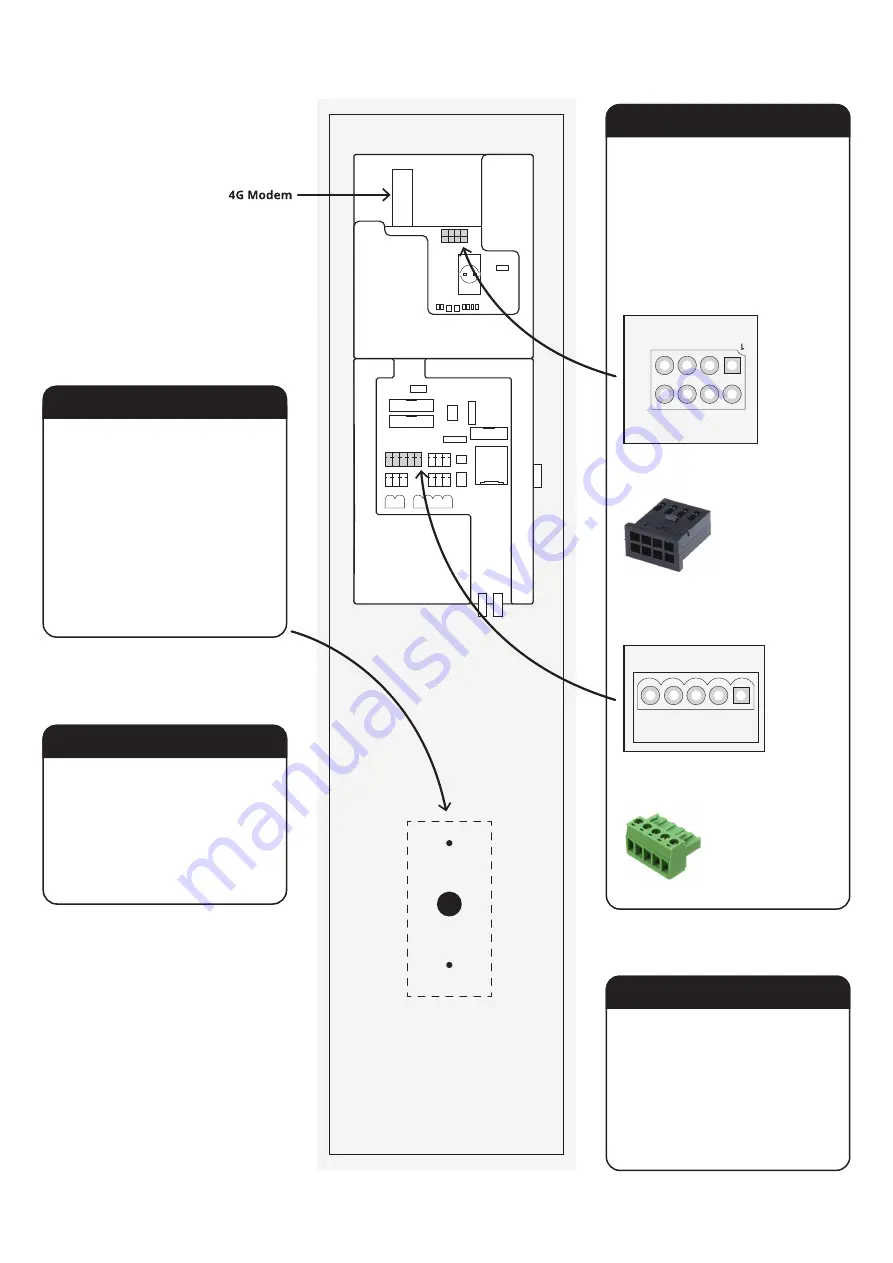
careful of the 4G modem.
Wire the Reader
OSDP (RS485)
The cabinet is capable of accepting
inputs from Wiegand or OSDP devices.
Every reader is different, so follow the
manufacturer’s instructions and connect
it to the appropriate point on the
control unit.
Reattach Control Unit
Connect the control unit back to the
cabinet by inserting the pins into the
hinges.
Plug all of the other cables back in
following the diagram on the previous
page.
Close the cabinet door.
Use 8 pins, 2 rows, 2.54mm pitch.
TE Connectivity, AMPMODU MOD II Female
RS485_CONN
GND
5V
A
B
GND
12V
B
A
Wiegand
Rear of Control Unit Panel
Use 5 pin, 3.81mm pitch
Wurth Elektronik 361 Pluggable Terminal Block
CARD_BIO1
D1
D0
GND
+5V
+12V
TORUS
Installation Guide
11


