EN - 3
E N
Hydraulic connections
The coils are equipped with flare nut connections, air vent and drain.
The CIAT hydraulic unions are equipped with a flange to maintain the gasket in position during tightening. The table below gives
the CIAT recommendation concerning the gaskets to use.
The hydraulic connections are made on the left or the right of the unit when looking at it from the front. Bottom inlet, top outlet.
For use with 2-pipe/2-wire coil, we advise installers against the use of PER piping for connections. In case of overheating, an
important rise of the temperature is possible.
This one can deteriorate characteristics of the PER up to the blow-out.
On units equipped with two coils (4 pipe installation), in the air direction the heater is located before the cooling coil (unless
otherwise specified).
To avoid any risk of condensation when using chilled water, it will be necessary to insulate the pipework, ensuring that it is vapour
sealed.
The condensed water is drained by a copper tubing with an external diameter of 16 mm.
The drainage pipework can be separate for each unit or connected to a main drain.
Use a 16 mm diameter transparent evacuation tube, with a minimum slope of 2 cm/m, with a constant difference in level along
its path.
Provide a siphon of at least 5 cm to prevent any discharge of gas or unpleasant odours.
Mounting of accessories
Presentation
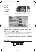
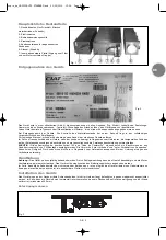
The plenum is an accessory which is to be mounted on the UTA either on the air discharge or on the air return side ; it is fitted
with circular couplings connected to flexible ducts orientated toward air diffusers or air return grilles (not supplied by CIAT).
The plenum is fitted with circular couplings :
DN 200 for UTAs 370-22/44
DN 250 for UTAs 370-44, 370-66
The plenum is insulated with melamine foam, coated with an aluminium veil. The circular couplings are obturated by the melamine
foam and will be opened as a function of the installation configuration.
Routing of connectors
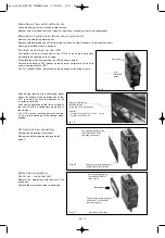
Routing of connectors will be performed with a cutting
tool, following the internal profile of these connectors,
and holding the melamine foam from the inside to
prevent it from unsticking.
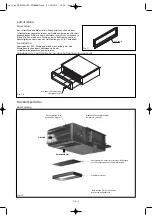
Positioning
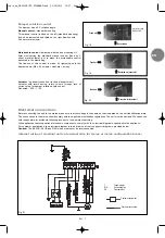
1- Position the centering studs before
mounting the plenums.
2- Positioning of the PVC gasket on the
external perimeter for correct sealing
between plenum and UTA.
Recommended gaskets
Diameter
O-ring gasket
Rubber flat gasket
Fiber flt gasket
A
B
C
D
B
C
D
B
C
D
G 1/2”
2.5
19
14
2
19
13.5
1.5
19
13.5
G 3/4”
2.5
24
18
2
24
17.5
1.5
24
17.5
G 1”
2.5
30
24
2
30
24
1.5
30
24
Fig. 4
Fig. 5
Fig. 6
PVC gasket
copie_de_NA0033B UTA STANDARD.qxd 31/05/2010 15:07 Page 3


