CIAT POWERCIAT2 LX Instruction Manual Download Page 32


NA13.47 B 

 EN - 30 

11.1 Preliminary checks


Check the following points:
1.  Check that the network voltage matches the unit voltage 

and that its value remains within the authorised limits 
(+10% to -10% compared to rated voltage).

1. Check that the unit complies with the refrigeration and 

wiring diagrams.

2. Check that all components are as specified on the 

drawings.

3.  Check that all documents and safety devices required by 

applicable European standards are present.

4. Check that there is sufficient clearance around the 

system for maintenance and emergency purposes.

5.  Check that the clamps on all pipes are secure.
6. Check that the welds and seals are in good condition. 

Check there are no refrigerant leaks.

7. Check that all mechanical guards are in place and 

functional.

8.  Close the drain valve under the evaporator.
9. After opening the water circuit valves, make sure that 

water is flowing in the cooler while the pump is running.

11.2 Starting up the compressors


Before starting up, the hydraulic circuit must be drained. 
For this operation, the pump(s) must have been started up. 
To enable operation without triggering the 
compressor(s), all our machines are delivered with the 
parameter "compressor on authorisation" set to "NO". 
The operation can therefore be carried out with no risk of 
starting up the compressors by setting the machine control 
to the "ON" position.


Check that the discharge valves and liquid outlet valves 
are open.


Power up the crankcase heaters for the compressors 6 
hours before the compressors are to be started up.


Once the hydraulic circuit has been drained, set the 
"compressor authorisation parameters" to "YES" to 
authorise start-up.


Once the compressors have been started up, check:
1.  The operation of the water circulation controller.
2.  Touch the crankcases to make sure that the heaters are 

operating correctly (they should be warm).

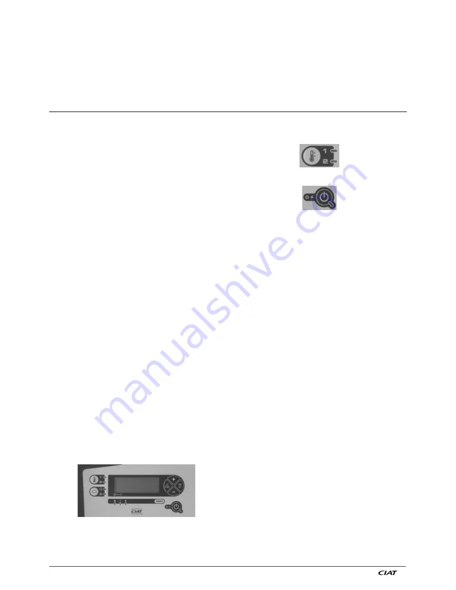
11.3 Starting up the unit


The system must have a heat load and water flowing in the 
exchangers when it is started up and tested.


-

1. Power up the main board


-

2. Check the configuration of the 

Xtraconnect 2


module.


-

3. Re-enter the setpoints.


-

4. Start the unit by pressing the On/Off button.


The internal safety devices are activated. If one of these 
safety devices is triggered, trace the fault, reset the safety 
device if necessary and press the RESET button on the 
console to clear the fault.


The unit will only start after 2 minutes (time required for 
inspection and acknowledgement of all safety devices). The 
control stages should operate in cascade mode, depending 
on the request.


Use either of the following to switch off the unit in non-
emergency situations:


-

The On/Off button on the console;


-

A dry contact on the automatic operation control.


Do not use the master switch as the electrical cabinet must 
remain live (frost protection, crankcase heater).

11.4 Post-start-up checks


Checking the compressors

1. Ensure that each compressor is rotating in the correct 

direction by checking that the discharge temperature 
rises quickly, the HP increases and the LP drops. If 
it is rotating in the wrong direction, the electric power 
supply is incorrectly wired (reversed phases). To restore 
rotation in the correct direction, swap the two power 
supply phases.

2.  Check the direction of rotation of the fans.
3. Check for any noise generated by the installation and 

remedy if necessary.

4. Check the compressor discharge temperature using a 

contact sensor.

5. Check that the absorbed current matches the values 

indicated on the compressor's data plate.

6. Check all safety devices to make sure they operate 

correctly.

7. During start-up and maintenance, the oil level must be 

checked; it must be visible in the sight glass, both at full 
load and power reduction.

8.  Only check the oil level in operation

.

11.  SYSTEM START-UP

The compressors are equipped with an automatic soft 
start system which reduces the starting torque and the 
acceleration times. This protects the mechanical parts 
and the motor, and substantially reduces the load on the 
system.


Intake valve (option)

The intake valve is used to isolate the compressor from the 
refrigerant when work is being carried out.

IMPORTANT

:


-

Make sure that the valves are fully open when the chiller 
is started up.


-

Check the tightness of the valve locking lever and make 
sure it is properly locked in order to ensure the valve is 
held in position. 

Summary of Contents for POWERCIAT2 LX

Page 1: ...POWERCIAT2 LX LXC AQUACIAT 2 Instruction manual 04 2014 N 13 47 B...

Page 2: ......

Page 3: ...n 15 8 3 Water quality 15 8 4 Sound level 15 8 5 Frost protection 15 8 6 Location 17 8 7 Anti vibration mounts for STD models optional 18 8 8 Anti vibration mounts for HEE models optional 22 9 CONNECT...

Page 4: ...EAN DIRECTIVES Machinery 2006 42 EC EMC 2004 108 EC Low voltage 2006 95 EC PED 97 23 EC Category 3 2500 to 3900 HEE models 2800 to 4800 STD models and category 4 4200 to 4800 HEE models 5600 and 6400...

Page 5: ...igned to operate with clean non corrosive fluids such as pure water soft water monoethylene glycol or monopropylene glycol Fluids such as brackish water seawater and demineralised water require a spec...

Page 6: ...rnal sensor B18 Hydraulic module indoor environment sensor A EVAPORATOR B TANK option C SINGLE PUMP D DOUBLE PUMP POWERCIAT2 LXC Based on the POWERCIAT2 LX LXC models incorporate a complete hydraulic...

Page 7: ...cabinet E Evaporator F Expansion vessel G Pump H Buffer tank LX C 5600X STD 6400X STD 4200X HEE 4500X HEE 4800X HEE A C D G C H E B F LX C 4200X STD 4800X STD 3200X HEE 3400X HEE 3600X HEE 3900X HEE A...

Page 8: ...tent litres 240 283 443 560 Hydraulic connection Flexible COLLAR DN 200 Flexible COLLAR DN 250 Max pressure water end bar 10 m3 h 71 241 77 241 83 241 90 241 96 241 111 241 124 241 136 383 145 383 Air...

Page 9: ...content litres 240 283 443 560 Hydraulic connection LX Flexible COLLAR DN 200 Flexible COLLAR 250 LXC Flexible COLLAR DN200 Max pressure water end bar 10 m3 h 63 241 70 241 77 241 83 241 89 241 95 24...

Page 10: ...ng heating element capacity W 500 820 Maximum rated current A 1 3 2 1 Pump module heating element capacity W 1500 Maximum rated current A 3 8 LXC FROST PROTECTION BUFFER TANK OPTION 1 Evaporator pipin...

Page 11: ...acity W 2 x 1500 Maximum rated current A 2 x 3 8 DESUPERHEATER FROST PROTECTION OPTION 1 Heat exchanger heating element power W 240 2 x 120 Maximum rated current A 0 6 2 x 0 3 REMOTE CONTROL AUXILIARY...

Page 12: ...5 15 10 8 0 6 45 48 40 Outdoor temperature C DB Evaporator water outlet C Glycol obligatory STANDARD STD version Low Noise Version STD LN Xtra Low Noise Version STD XLN A B C 15 20 10 0 10 30 8 5 15...

Page 13: ...eration with pure water B Full load operation must be with glycol C Operation without economiser Low Noise Version HEE LN Xtra Low Noise Version HEE XLN Partial load operation for outdoor temperature...

Page 14: ...ion minimum volume litres 2150 2351 2551 2727 2913 3312 3696 3987 4299 POWERCIAT 2 HEE 2500X 2800X 3050X 3200X 3400X 3600X 3900X 4200X 4500X 4800X installation minimum volume litres 1967 2172 2415 249...

Page 15: ...d and positioned by a specialist handling company using the appropriate standardised tools Before handling check that the path leading to the installation location is accessible and free from obstacle...

Page 16: ...X 5600X 9334 6203 1002 894 1631 2167 1083 2167 1083 2167 LX 6400X 9508 6269 993 896 1631 2167 1083 2167 1083 2167 LXC 2500X 6341 3962 1052 929 545 2167 2167 2174 LXC 2800X 6378 6939 3948 4358 1052 107...

Page 17: ...tipollution standards in force if connecting to a drinking water system 8 4 Sound level Our units are designed to operate at moderate sound levels for this type of equipment However when designing the...

Page 18: ...3 1 7 14 Propylene glycol Freezing point C 0 4 9 16 25 Minimum water outlet C 5 4 1 4 9 Important The values are given for guidance only according to the standard characteristics of the MEG These may...

Page 19: ...So that maintenance can be carried out on the chiller If the unit is likely to be subjected to winds of above 170 km h it must be fixed to the ground via the 21 mm holes on the base frame mounts and b...

Page 20: ...of failure to use the recommended mounts Location of mounts for sizes 2800X 3000X STD 2151 2251 50 50 700 236 700 6506 LX 2800X 3000X 700 380 700 700 700 380 380 380 380 2251 700 A 700 7598 LXC 2800X...

Page 21: ...00X 3600X SYLOMER 700 x 50 x 25 LXC A 3200 3400 3600 100 150 110 B 150 150 150 C 150 150 150 D 200 150 200 E 200 200 250 F 273 273 300 G 350 350 323 H 400 400 350 I 400 400 400 J 400 400 400 LXC A 320...

Page 22: ...4200 4800 200 200 650 700 650 700 600 650 442 442 350 350 250 200 250 200 200 150 150 150 J LXC A B C D E F G H I 700 384 326 700 700 700 700 700 540 700 700 700 640 520 410 300 680 640 A 700 700 700...

Page 23: ...D E F G H I 5600 6400 259 259 1200 1150 1100 1100 1000 1100 900 950 800 800 600 550 500 450 400 400 250 250 J LXC A B C D E F G H I 5600 6400 228 228 650 650 650 650 650 650 550 650 550 600 450 400 40...

Page 24: ...he unit the structure or the building in the event of failure to use the recommended mounts Location of mounts for sizes 2500X HEE LXC 2151 2251 50 50 700 258 700 6506 LX 2500X 700 350 700 700 700 380...

Page 25: ...800X 3050X SYLOMER 700 x 50 x 25 LXC A 2800 3050 400 100 B 500 500 C 500 500 D 500 500 E 200 500 F 120 120 G 113 113 H 110 110 I 110 110 J 110 110 LXC A 2800 3050 650 240 220 500 700 700 750 700 700 7...

Page 26: ...0 x 50 x 25 SYLOMER 700 x 50 x 25 2151 50 50 2151 50 50 2251 11940 LXC 3200X 3400X 3600X 3900X SYLOMER 700 x 50 x 25 700 400 506 700 700 700 700 700 400 700 700 700 550 450 350 250 650 700 164 700 700...

Page 27: ...YLOMER 700 x 50 x 25 2151 50 50 2151 50 50 2251 14112 LXC 4200X 4500X 4800X SYLOMER 700 x 50 x 25 700 650 550 400 550 400 450 350 350 400 700 700 700 700 700 700 700 700 700 600 700 650 650 650 650 65...

Page 28: ...the necessary systems for filling and draining the energy transfer fluid The piping must not transmit any force or vibrations to the evaporator The pump s must be slaved to the unit auxiliary operati...

Page 29: ...Hydraulic connections configuration and precautions To ensure that the unit is commissioned and operates under the right conditions the desuperheater water loop must be as short as possible This will...

Page 30: ...etc and vice versa For more information refer to the Master Slave management section in the Xtraconnect 2 control manual 10 CONTROL 9 5 Electrical connections All wiring must be connected in accordanc...

Page 31: ...circuit concerned shuts down and the fault is indicated by a message and the illumination of a red LED on the console Overpressure protection Each refrigeration circuit in each unit is equipped with a...

Page 32: ...le 3 Re enter the setpoints 4 Start the unit by pressing the On Off button The internal safety devices are activated If one of these safety devices is triggered trace the fault reset the safety device...

Page 33: ...e must be added to each circuit in the unit Repeat these steps if the subcooling temperature is below the specified values NB an excessively low suction pressure or an excessively high condensation pr...

Page 34: ...of the system The lubricating oil and the low temperature liquid refrigerant in particular may cause inflammation similar to burns if they come into contact with skin or eyes Store unused refrigerant...

Page 35: ...under or around the unit and listen for any unusual noises LP compressor suction pressure HP compressor discharge pressure the water inlet and outlet temperatures in the exchangers the charge via the...

Page 36: ...ipate future trips Perform the checks listed in the table below if you notice that a magnitude deviates from its normal value and gradually moves closer to the safety limit Faults Probable cause Solut...

Page 37: ...in force Check whether any part of the unit can be recycled for another purpose 14 3 Fluids to be recovered for treatment R134a refrigerant Energy transfer fluid depending on the installation water gl...

Page 38: ...ature C Air inlet temperature C Air outlet temperature C Evaporator Water inlet temperature C Water outlet temperature C Liquid inlet temperature C Evaporator outlet temperature C Date Time Nominal vo...

Page 39: ...EN EN 37 NA13 47 B...

Page 40: ...NA13 47 B EN 38...

Page 41: ......

Page 42: ...roc der sans pr avis toutes modifications techniques Non contractual document With the thought of material improvement always in mind CIAT reserves the right without notice to proceed with any technic...

Reviews: