


EN - 10
5.7 - Gasket replacement
- Before starting, check the manufacturing date of the gaskets, printed on the relevant date stamp (Fig.5). Please
note that the gaskets must not be stored for more than 6-12 months (see chapter 2 - STORAGE).
- Remove the old gasket without using cutting tools, which could irreparably damage the plate.
- Make sure that the plate and gasket are thoroughly clean and dry alongside the gasket slot.
5.7.1 - Plug-In® Design gaskets
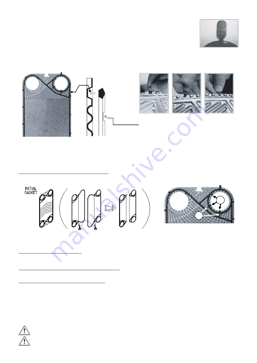
Press the gasket onto the plate (Fig. 6), making sure that the leak detector vents, "A", are facing up and check that the Plug-In®
tabs are hooked into their respective notches (Fig.7). Make sure that the gasket is properly seated in its notch, then turn the plate
over to check again that all the Plug-In® tabs are correctly in place.
Fig.5
5.7.2 - Plug-In® Design gaskets which may require the use of glue
Plug-In® Design gaskets, for initial plates, intermediate turning plates (for multi-pass heat exchangers only) and final plates, may require
a limited use of glue.
These types of plates, complete with gaskets mounted at the factory, can be supplied as spare parts. Alternatively, for the substruction of
the gaskets, proceed as described below.
Initial plate
Models which do not provide a dedicated initial gasket:
1) Cut two gaskets along the vertical axis and use the two parts with sealing rings inside the holes (Fig.8) to form a complete initial gasket.
Discard the other two halves.
2) The half of the gasket for which it is possible to correctly place all Plug-In® tabs in their corresponding notches, can be mounted as described
in 5.7.1.
3) On the other half, use shears to remove all the Plug-In® tabs and, if present, all the connecting bridges between the diagonal and the sealing
ring (Fig.9 b). So, following the procedure described in point 5.7.3, attach the gasket, excluding the sealing rings.
Models with a dedicated initial gasket: no cutting is necessary; attach the gasket according to the procedure described in point 5.7.3.
Again, do not attach the sealing rings.
Intermediate turning plate (for multi-pass heat exchangers only) and end plate
Models equipped with Plug-In® tabs inside the sealing rings: using shears, cut the Plug-In® tabs inside the sealing rings (Fig. 9 c)
corresponding to the closed holes only.Then, following the procedure described in point 5.7.3, attach only the connecting bridges between
the diagonal and the ring.
Models without Plug-In® tabs inside the sealing rings: no cutting is necessary; proceed as described in point 5.7.1.
Note: On some models it might be necessary to remove all the Plug-In® tabs (not only those inside the sealing rings). In this case, if
permitted, remove the entire gasket.
Note: For the PWB 65 model it is recommended, if permitted, to attach the entire gasket.
5.7.3 - Gluing
1) Using the appropriate epoxy glue (supplied as a spare part, on request), spread a strip of glue (2-3 mm) onto the plate in the gasket slot.
2) Leave to dry for 5 minutes in a suitably ventilated room, then position the gasket on the plate, making sure that it is perfectly contained
in the slot and that there is no excess glue escaping from the slot.
3) Place a counterweight on the glued plates (without deforming the plastic), ensuring that the whole gasket is evenly compressed for at
least 2 hours.
N.B. Some particular standards (e.g. ACS Attestation de Conformité Sanitaire) may prohibit direct contact between fluid and
glue. If this is the case, do not glue the parts of the gasket which could come into direct contact with the fluid.
WARNING: Always follow the mandatory general standards for personal protection, in particular: avoid contact with the eyes,
use an appropriate protective mask to protect against inhalation hazards and wear gloves.
Fig.7
Fig.6
b
c
Fig.8
Fig.9
A: Leak detector vents are notches in the surfaces of the gasket sections around the portholes which
vent any leaks to the atmosphere so that they can be detected.
Summary of Contents for ITEX NA 10.51 D
Page 2: ......