


©
CIAS Elettronica S.r.l.
Ed. 1.2
Installation Manual
Page
32
of
47
MICRO-RAY
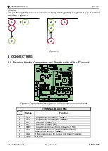
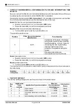
Corners
The positioning in the corners is carried out side by side by placing the type A or type B columns
as shown in figure 10.
Figure 10
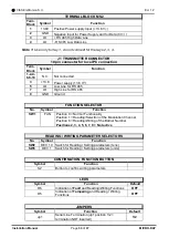
3 CONNECTIONS
Terminal blocks, Connectors and Functionality of the TX circuit
Figure 11 Topographical arrangement of the components in the circuit
TERMINAL BLOCK MS1
Term.
Block Symbol
Function
1
TMP
Tamper Relay Contact (C) -
Note 1
2
TMP
Tamper Relay Contact (NC) -
Note 1
3
FLT
Fault Relay Contact (C)
4
FLT
Fault Relay Contact (NC)
5
STBY
Tamper Column Input (Norm. Closed to GND)
6
TEST
Power Presence Input (Norm. Closed to GND)
(Open when not used) -
Note 1
7
GND
Reference potential for Tamper and Power Presence
8
SYNC
Not used
1
MS1
T
M
P
T
M
P
B
B
B
B
A
A
A
A
Summary of Contents for MICRO-RAY
Page 51: ...NOTE...


