


©
CIAS Elettronica S.r.l.
Ed. 1.2
Installation Manual
Page
28
of
47
MICRO-RAY
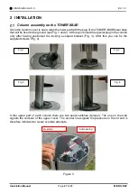
Base template of the column
Figure 6
File eventually available in 1:1 scale
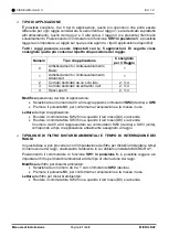
Column composition
All microwave rays are assembled in the factory at preset heights (based on the model chosen),
but then they can be moved according to the needs of the field.
The barrier is composed of two columns, each one can contain up to 4 rays (only for 3m tower)
always identified with the letter "A" for one column and the letter "B" for the other.
The rays are always coupled and identified as indicated in the table below, in the event of
maintenance or replacement of a ray (or part of it), it will be necessary to follow mandatory
the chart.
Incorrect positioning leads to system malfunctions.
No further combinations are possible.
Ray
number
Column "A" Ray number
Column "B" Ray number
Height
above the
ground (from
antenna
centre)
4
R4-A
P/N 20KIMRA0004 (RX)
R4-B
P/N 20KIMRB0004 (TX)
270 cm
3
R3-A
P/N 20KIMRA0003 (RX)
R3-B
P/N 20KIMRB0003 (TX)
170 cm
2
R2-A
P/N 20KIMRA0002 (TX)
R2-B
P/N 20KIMRB0002 (RX)
90 cm
1
R1-A
P/N 20KIMRA0001 (TX)
R1-B
P/N 20KIMRB0001 (RX)
40 cm
Note: Consider the real height of the base and then adjust ray 1 so that the antenna centre is
40 cm above the ground.
Caution: The minimum height, from the ground, of RAY 1 cannot be less than 35 cm.
Summary of Contents for MICRO-RAY
Page 51: ...NOTE...


