background image


CIAS Elettronica S.r.l. 


Ed.

.2.4


Installation Manual 

Pag. 33 of 36 

Murena/Murena-Plus24 

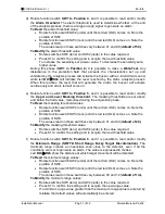
j)  Rotate function switch 

SW1 to Position A

 and it is possible to read and/or modify the 

Maximum Target Size.


To Read

 the maximum target size value: 

  Rotate function switch SW2 (units) until the red led (DL9) comes on. Note the 

position of SW2. 

  Rotate function switch SW3 (tens) until the red led (DL8) comes on. Note the 

position of SW3. 
The values read on these switches vary between 01 and 99 (

default of 70

). 

To Modify

 the maximum target size value: 

  Rotate switches SW3 (tens) and SW2 (units) to the value required. 


Press S1 to confirm the setting and to acquire the new maximum size. 


k)  Rotate function switch 

SW1 to Position 0 and press button S1

. This concludes the 

installation phase.  
Leave the switch in this position for normal operation. 

4.2  Calibration using Software 

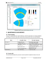
For  display  and  extremely  accurate  management  of  all  the  parameters  of  the  detector, 
complete  with  analogue  threshold  levels  and  received  signals,  use  the 

Wave-Test  2


software running on a PC. Refer to the software manual for connection details and detailed 
procedures for the management of the detector.  


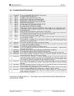
Analogue Values screenshot for Murena, Murena Plus and Murena Plus Curtain 


Summary of Contents for Murena

Page 1: ...RENA Rivelatore Doppler ad elaborazione digitale per protezioni esterne Manuale d installazione Doppler detector with digital processing for external protection Installation Manual Edizione Edition 2...

Page 2: ...el Circuito 8 3 2 Collegamento all Alimentazione 10 3 3 Collegamento alla Centrale 10 3 3 1 Contatti di Allarme 11 3 3 2 Connessioni per Stand By 11 3 3 3 Connessioni per Test 11 3 4 Linea Seriale RS...

Page 3: ...tors and Circuit Functions 25 3 2 Power Supply Connections 27 3 3 Connections to the Control panel 27 3 3 1 Alarm Contacts 28 3 3 2 Stand by Connections 28 3 3 3 Test Connections 28 3 4 Serial Line RS...

Page 4: ...fici assicurando un efficace vigilanza contro l intrusione L utilizzo di un potente DSC consente di generare i dati da analizzare utilizzando le pi avanzate tecniche sia nel dominio del tempo che nel...

Page 5: ...llarmi Leds Distanza Massa Portata Amplificatori Doppler Amplificatore di Trasmissione Demodulatore sincrono di Ricezione Modulatore di Trasmissione S H S H O L J5 Microprocessore Ingresso Comando Tes...

Page 6: ...a sfondamento per il montaggio del secondo passacavo Figura 1 2 2 Accessori Gli accessori del rivelatore Murena sono i seguenti Staffa a muro 10 cm Staffa a muro 30 cm Staffa a muro 40 cm Staffa da pa...

Page 7: ...orescenti che non sia posizionato di fronte a ventole specialmente metalliche le quali con il movimento delle loro pale potrebbero generare segnali indesiderati Murena pu lavorare in abbinamento a tut...

Page 8: ...ERTICALE L altezza di installazione consigliata per Murena Curtain in configurazione tenda da 2 5 a 4m con utilizzo parametri standard L ampiezza del campo protetto per Murena Plus 24 si sviluppa sul...

Page 9: ...rcuito Murena MORSETTIERA MS1 Mors Simbolo Funzione 1 AL Contatto Rel di Allarme C 2 AL Contatto Rel di Allarme NC 3 TMP Contatto Rel di Manomissione C 4 TMP Contatto Rel di Manomissione NC 5 FLT Cont...

Page 10: ...Funzioni OFF 2 DL2 Visualizzazione dinamica delle Funzioni OFF 3 DL3 Visualizzazione dinamica delle Funzioni OFF 4 DL4 Visualizzazione dinamica delle Funzioni OFF 5 DL5 Visualizzazione dinamica delle...

Page 11: ...a lunghezza del collegamento ed all assorbimento dell apparato Nel caso in cui i collegamenti risultassero troppo lunghi si consiglia l utilizzo di un alimentatore supplementare Connettere i fili di a...

Page 12: ...ita e il relativo contatto si apre quando la tensione di alimentazione minore di 11 5 Vcc o maggiore di 14 8 Vcc oppure la temperatura all interno del contenitore sia inferiore 30 C o maggiore di 65 C...

Page 13: ...egli eventi di storico e monitor registrati nel rivelatore 3 4 1 Connessioni per Linea Seriale RS 485 Il collegamento pu essere di tipo Multidrop possono cio essere connessi pi sensori in parallelo su...

Page 14: ...n solo led acceso b Ruotare il commutatore di funzione SW1 in posizione 2 Impostare i commutatori SW3 decine e SW2 unit sul valore 0 assicurarsi in questa operazione di non avere ostacoli e di non ess...

Page 15: ...ne 5 possibile leggere e o modificare il valore della soglia di mascheramento superiore ed inferiore Le soglie di mascheramento sono poste una sopra ed una sotto il valore di campo memorizzato durante...

Page 16: ...assegnato Ruotare il commutatore SW2 unit fino a che il led rosso DL9 sia acceso Ruotare il commutatore SW3 decine fino a che il led rosso DL8 sia acceso Il valore letto su questi due commutatori vari...

Page 17: ...atori SW2 unit e SW3 decine sul valore desiderato premere S1 per confermare l acquisizione e la messa in uso della nuova dimensione massima k Ruotare il commutatore di funzione SW1 in posizione 0 e pr...

Page 18: ...ensione alta e o bassa Verificare la tensione di alimentazione Temperatura alta e o bassa Verificare la temperatura del rivelatore Led Allarme acceso Movimento od ostacoli nel campo protetto Assicurar...

Page 19: ...mA 75 140 Contatto allarme intrusione Rel Statico 100mA C NC Contatto manomissione Rel Statico 100mA C NC Contatto di guasto Rel Statico 100mA C NC Led rosso per Allarme intrusione off Led rosso per...

Page 20: ...IB System 16 Attivazione Di tre leds di segnalazione allarme manomissione guasto Attivazione Di 6 led multifunzionali per mostrare la distanza o la dimensione del bersaglio o il raggiungimento della...

Page 21: ...ion in the differences in sensitivity between movements longitudinal and transverse to the lobes of protection characteristic in most Doppler effect sensors This performance is then enhanced by subseq...

Page 22: ...Leds Distanza Massa Portata Amplificatori Doppler Amplificatore di Trasmissione Demodulatore sincrono di Ricezione Modulatore di Trasmissione S H S H O L J5 Microprocessore Ingresso Comando Test Ingre...

Page 23: ...the base for the mounting of a second gland Figure 1 2 2 Accessories The following accessories are available for the Murena sensor Wall Bracket 10 cm Wall Bracket 30 cm Wall Bracket 40 cm Post Bracke...

Page 24: ...er accessories that it is not looking directly at fluorescent lights and that it is not positioned in front of fans or vents especially metal with movable vanes that can generate unwanted signals Mure...

Page 25: ...e VERTICAL Plane Detection Lobe Using default parameters suggested height of installation for Murena Curtain is from 2 5 to 4 mt The size of detection for Murena Plus 24 has an amplitude of 45 on hori...

Page 26: ...functions for the Murena board TERMINAL MS1 Term Symbol Function 1 AL Alarm Relay Contact C 2 AL Alarm Relay Contact NC 3 TMP Tamper Relay Contact C 4 TMP Tamper Relay Contact NC 5 FLT Fault Relay Co...

Page 27: ...1 DL1 Dynamic function display OFF 2 DL2 Dynamic function display OFF 3 DL3 Dynamic function display OFF 4 DL4 Dynamic function display OFF 5 DL5 Dynamic function display OFF 6 DL6 Dynamic function di...

Page 28: ...of the conductors calculated based on the length of the connection and the current requirements of the apparatus For very long connections a supplementary power supply is recommended Connect the 13 8...

Page 29: ...ontact opens when the power supply voltage is outside the limits of 11 5Vdc and 14 8Vdc or the internal temperature is outside the limits of 30 C and 65 C The Murena can easily be connected to any con...

Page 30: ...arget size and the acquisition of the History and Monitor events stored in the detector 3 4 1 RS 485 Serial Line Connections The connection can be of the Multi drop type making it possible to connect...

Page 31: ...Rotate switches SW3 tens and SW2 units till 0 value ensuring during this operation that there are no obstacles in front of the detector to ensure accurate acquisition Press button S1 to start the acqu...

Page 32: ...to read and or modify the Upper and Lower Masking threshold The masking thresholds are set above and below the field value memorised during the acquisition phase To Read the masking threshold values...

Page 33: ...ues Rotate function switch SW2 units until the red led DL9 comes on Note the position of SW2 Rotate function switch SW3 tens until the red led DL8 comes on Note the position of SW3 The values read on...

Page 34: ...et size value Rotate switches SW3 tens and SW2 units to the value required Press S1 to confirm the setting and to acquire the new maximum size k Rotate function switch SW1 to Position 0 and press butt...

Page 35: ...Possible Solution Fault Led on Voltage high or low Check power supply voltage Temperate high or low Check detector temperature Alarm Led on Movement or obstacles in the protected area Ensure that the...

Page 36: ...consumption normal with serial mA 75 140 Intrusion Alarm Contact Static Relay 100mA C NC Tamper Alarm Contact Static Relay 100mA C NC Fault Alarm Contact Static Relay 100mA C NC Red Led for Intrusion...

Page 37: ...interface 16 Activation Of three leds for the indication of alarm tamper and fault Activation Of 6 multi functional led to show the distance or dimensions of the target or entering alarm condition Ac...

Page 38: ...NOTE...

Page 39: ...NOTE...

Page 40: ...crease the separation between the equipment and receiver Connect the equipment into an outlet on a circuit different from that to which the receiver is connected Consult the dealer or an experienced r...

Reviews: