CIAS Elettronica S.r.l.
Ed.
.2.4
Installation Manual
Pag. 27 of 36
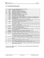
Murena/Murena-Plus24
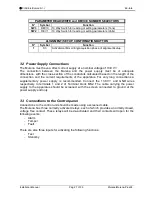
PARAMETER READ/WRITE and DEVICE NUMBER SELECTORS
N°
Symbol
Function
SW3
DEV10
10 Way Switch for reading or setting parameters (Tens)
SW2
DEV1
10 Way Switch for reading or setting parameters (Units)
ALIGNMENT/SET UP CONFIRMATION BUTTON
N°
Symbol
Function
1
S3
Activate/confirm writing/acquisition phase of alignment/setup
3.2 Power Supply Connections
The Murena must have a direct current supply at a nominal voltage of 13.8 V
.
The connection between the Murena and the power supply must be of adequate
dimensions, with the cross-section of the conductors calculated based on the length of the
connection and the current requirements of the apparatus. For very long connections a
supplementary power supply is recommended. Connect the 13.8V
and GND wires
respectively to terminals 1 and 2 of Terminal block MS2. The cable carrying the power
supply to the apparatus should be screened, with the screen connected to ground at the
power supply end only.
3.3 Connections to the Control panel
Connections to the control unit should be made using a screened cable.
The Murena has three normally activated relays, each of which provides a normally closed,
voltage free contact. These relays will be de-activated and their contacts will open for the
following events:
-
Alarm
-
Tamper
-
Fault
There are also three inputs for activating the following functions:
-
Test
-
Stand-by
Summary of Contents for Murena
Page 38: ...NOTE...
Page 39: ...NOTE...

