


Page 31
The encoder power consumption imposes additional drain on battery-powered outstations, so it is optimised by pulsing
power when the shaft is stationary. If movement is detected power is maintained until the shaft again becomes
stationary. By this means the average power consumption of the shaft encoder is reduced to approximately that of
Nano_Link
itself. This means that the battery life will be about halved if
Nano_Link
is powering a shaft encoder, and
reduced to one third if it is powering two shaft encoders.
The signals from an incremental shaft encoder only indicate movement up and down from an arbitrary starting point. A
shaft encoder does not have an in-built zero reference. The facility to set the zero is therefore built into the outstation,
as described below
Digital and analogue outputs are not available on versions with a shaft encoder interface.
9.2.3 Hardware Configuration
Nano_Link
sources 5VDC at 100mA max to the shaft encoder via digital
outputs 3 and 4. Special hardware in
Nano_Link
changes the function of
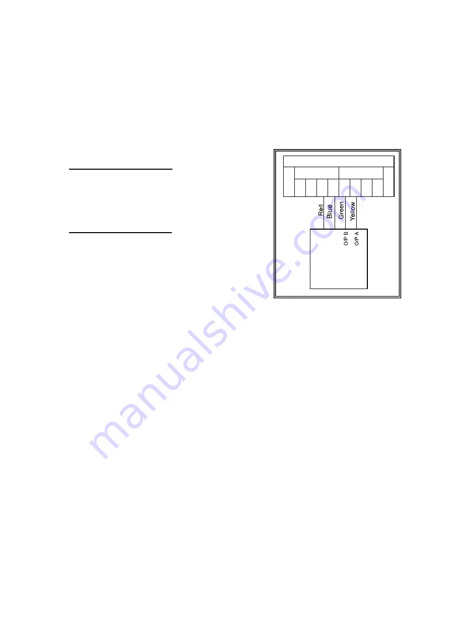
these from volt-free contacts to power outputs. Connections to a Thistle
24R series encoder are as shown:
9.2.4 Software Configuration
A
Nano_Link
outstation with a shaft encoder interface must be fitted
with an Alphanumeric Display Module. Shaft encoders are enabled
and disabled through the display module, and the zero is set through
it. The means of doing this is described in sections 10.2.1 and
10.2.2.
Thistle 24R
Encoder
D I G I T A L S
1-4
O U T P U T S
I N P U T S
1-4
COM
1
2
3
4
1
2
3
4
COM
+ -
Summary of Contents for Nano Link IP67
Page 40: ...Page 38...