


Page 15
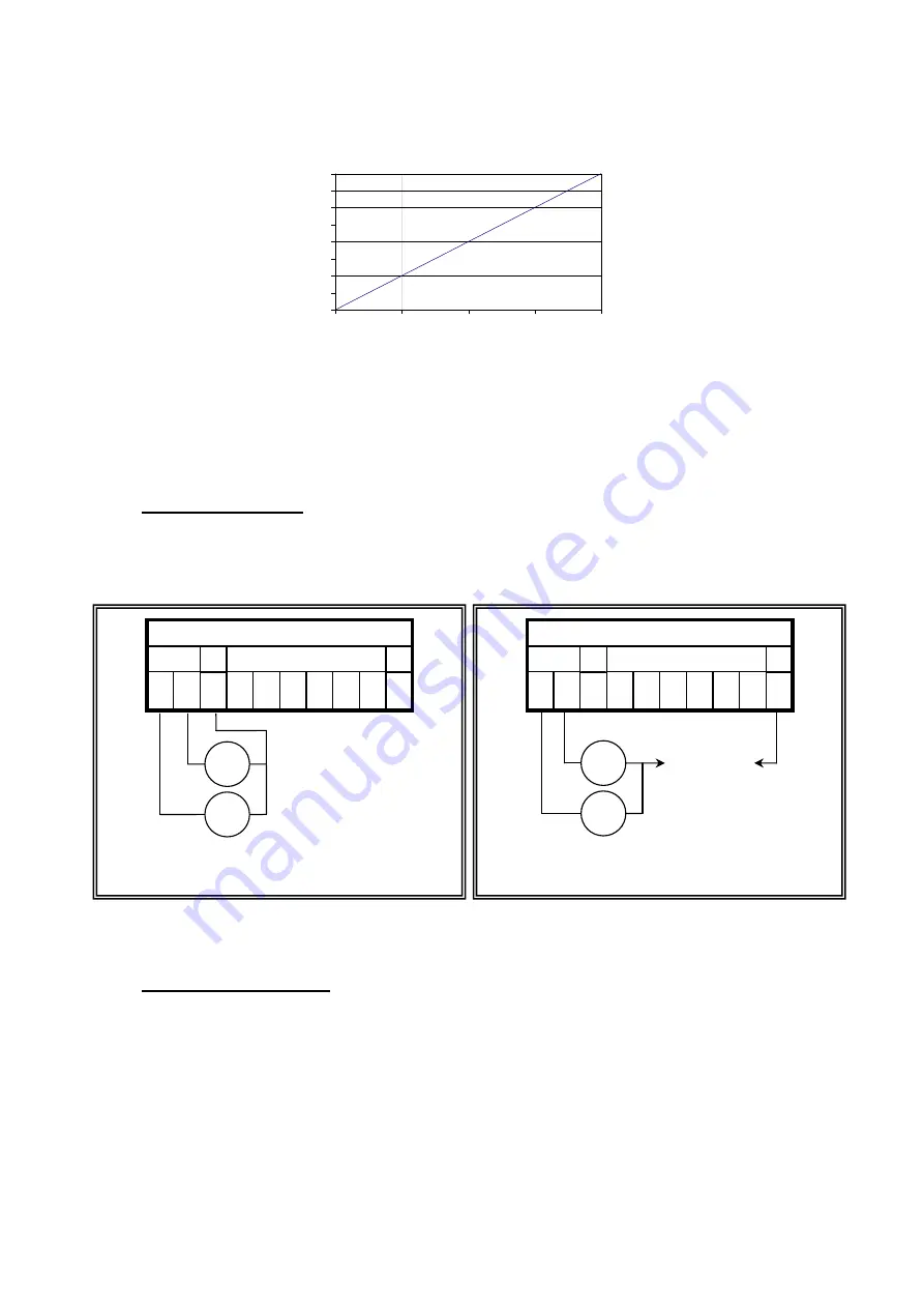
This can be illustrated graphically as follows:
The calculated value can be read via
Micro_Link
. If using method 3 above. However, if using method 1 or 2 the value
will be scaled appropriately.
The radio receiver has a sensitivity of about -10dB
V, and a good radio path should have a margin of at least 10dBµV
so the RSSI should ideally read at least 0dBµV, or 1500.
3.4.4 Analogue Outputs
Analogue outputs, if equipped, sink a current of 0…20.00mA to the internal 0V rail. The current can be sourced from
either the internal 12V supply on the + terminal of the analogue connector, or from an external supply of up to 24V DC.
Analogue outputs are only available when the 12V supply is active, so
Nano_Link
must be set to continuous power
(switch 2.8 closed):
Although the outputs are calibrated to give 0…20.00mA, they can produce up to 20.40mA to indicate fault conditions.
3.4.5 Expansion Capability
Nano_Link
includes an
I/O_bus port
that can be used to access expansion modules from the
Data_Link 2000
product
range. Its capacity is limited to one 16-way digital input module (must be set to address 0, so S1.1…S1.5 all open), one
16-way digital output module (must be set to address 1, so S1.1…S1.4 all open, S1.5 closed) and/or an Alphanumeric
Display Module. Digital expansion modules cannot be used on battery-powered
Nano_Link
’s. The Alphanumeric
Display Module is described in Chapter 10.
-15
-10
-5
0
5
10
15
20
25
0
1000
2000
3000
4000
Value
RSSI (dBuV)
A N A L O G U E S
O / P
I N P U T S
1 -
2 -
+
1 -
1 I
1 +
2 -
2 I
2 +
-
Outputs powered by
Nano_Link
Load 0…450
- +
- +
A N A L O G U E S
O / P
I N P U T S
1 -
2 -
+
1 -
1 I
1 +
2 -
2 I
2 +
-
Outputs powered by external supply
Load 0…((V-1)*50)
- +
- +
+10…24V 0V
External Supply
Summary of Contents for Nano Link IP67
Page 40: ...Page 38...