Chrysler Concorde 1993 Service Manual Download Page 57

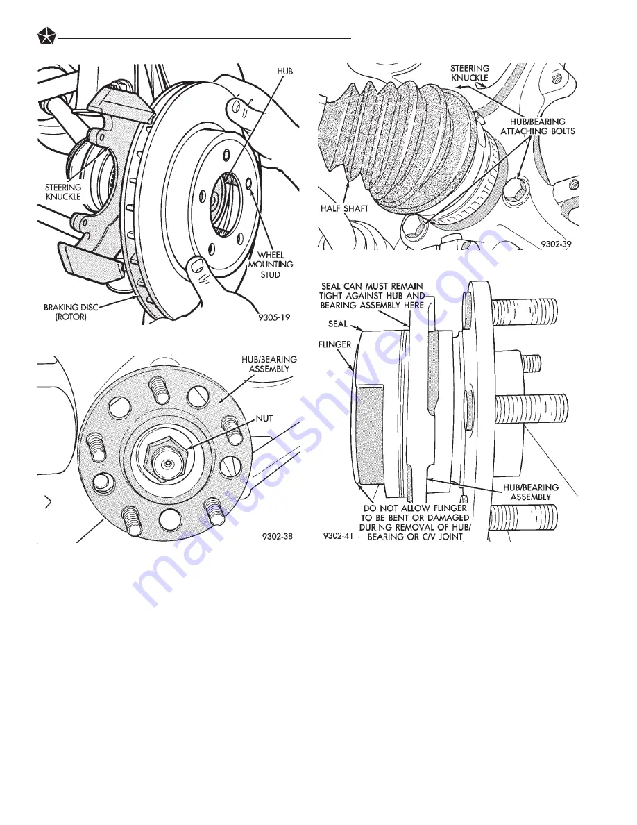
(7) Remove hub and bearing assembly from steer-

ing knuckle, by sliding it straight out of steering
knuckle and off end of stub axle (Fig. 6). If hub and
bearing assembly will not slide out of knuckle. Insert
a pry bar between hub and bearing assembly and
steering knuckle (Fig. 7) and gently pry hub and
bearing from knuckle. If stub shaft is frozen to hub
and bearing assembly tap end of stub shaft with soft
face hammer to free it from hub and bearing spline.

INSTALLATION

CAUTION: Hub and bearing assembly mounting
surfaces on steering knuckle (Fig. 8) must be
smooth and completely free of foreign material or
nicks.

CAUTION: When installing hub and bearing assem-
bly into steering knuckle, be careful not to damage
the flinger disc (Fig. 5) on hub and bearing assem-
bly. If flinger disc becomes damaged, hub and bear-
ing assembly MUST not be used and MUST be
replaced with a new hub and bearing assembly.

(1) Install hub and bearing assembly onto stub

shaft and into steering knuckle until squarely seated
on face of steering knuckle. (Fig. 6).

(2) Install the 3 hub and bearing assembly to

steering knuckle attaching bolts (Fig. 9). Equally
tighten all 3 mounting bolts until hub and bearing
assembly is squarely seated against front of steering
knuckle. Then torque all 3 hub and bearing assembly
mounting bolts to 110 N

I

m (80 ft.lbs.).

Fig. 2 Removing Braking Disc

Fig. 3 Hub And Bearing To Stub Axle Retaining Nut

Fig. 4 Hub And Bearing Assembly Retaining Bolts

Fig. 5 Hub And Bearing Assembly Seal

SUSPENSION AND DRIVESHAFTS

2 - 35

Summary of Contents for Concorde 1993

Page 1: ...R TRANSMITTED IN ANY FORM OR BY ANY MEANS ELECTRONIC ME CHANICAL PHOTOCOPYING RECORDING OR OTHERWISE WITHOUT THE PRIOR WRITTEN PERMISSION OF CHRYSLER CORPORATION Chrysler Corporation reserves the right to make changes in design or to make additions to or improvements in its products without imposing any ob ligations upon itself to install them on its products previously manufactured Litho in U S A...

Page 2: ...to a solid tab on the first page of each group The first page of the group has a contents section that lists major topics within the group Throughout this manual the vehicle family code LH is used when descriptions or procedures apply to all three models Concorde Intrepid and Vision Tightening torques are provided as a specific value throughout this manual This value represents the midpoint of the...

Page 3: ...oling System 8 Electrical 9 Engines 11 Exhaust System and Intake Manifold 13 Frame and Bumpers 14 Fuel System 19 Steering 21 Transaxle 22 Wheels and Tires 23 Body Components 24 Heating and Air Conditioning 25 Emission Control Systems Component and System Index Service Manual Comment Forms Rear of Manual ...

Page 4: ......

Page 5: ...e following conditions it is considered severe service Extremely dusty areas 50 or more of vehicle operation in 32 C 90 F or higher temperatures Prolonged idling such as vehicle operation in stop and go traffic Frequent short running periods Not allowing en gine to warm to operating temperatures Police or taxi usage FUEL USAGE All Chrysler Corporation engines require the use of unleaded fuel to re...

Page 6: ...on vehi cle require no periodic maintenance Some compo nents are sealed and permanently lubricated Rubber bushings can deteriorate or limit damping ability if lubricated The following list of components require no lubrication Air Pump Generator Bushings Drive Belts Drive Belt Idler Tensioner Pulley Wheel Bearings Rubber Bushings Starter Bearings Bushings Suspension Strut Bearings Throttle Control ...

Page 7: ...LUBRICATION AND MAINTENANCE SCHEDULES LUBRICATION AND MAINTENANCE 0 3 ...

Page 8: ...l accessories Keyless Entry system must be turned OFF manually 4 Connect jumper cables to booster battery RED clamp to positive terminal BLACK clamp to negative terminal DO NOT allow clamps at oppo site end of cables to touch electrical arc will result Fig 1 Review all warnings in this procedure 5 On disabled vehicle connect RED jumper cable clamp to positive terminal Connect BLACK jumper cable cl...

Page 9: ...ways use a safety chain system that is indepen dent of the lifting and towing equipment Do not allow any of the towing equipment to con tact the fuel tank of the vehicle being towed Do not go under the vehicle while it is lifted by the towing equipment Do not allow passengers to ride in a vehicle being towed Always observe all state and local laws pertaining to warning signals night illumination s...

Page 10: ...ith the rear end lifted If damage to the vehicle prevents front towing use a flat bed towing device CAUTION Do not push the vehicle with another ve hicle as damage to the bumper facia and transaxle can result Fig 4 Towing 0 6 LUBRICATION AND MAINTENANCE ...

Page 11: ...TION CAN BE HAZARDOUS TO YOUR HEALTH THOROUGHLY WASH EX POSED SKIN WITH SOAP AND WATER DO NOT WASH SKIN WITH GASOLINE DIESEL FUEL THINNER OR SOLVENTS HEALTH PROB LEMS CAN RESULT DO NOT POLLUTE DISPOSE OF USED ENGINE OIL PROPERLY CONTACT YOUR DEALER OR GOVERNMENT AGENCY FOR LOCATION OF COL LECTION CENTER IN YOUR AREA BREAK IN PERIOD CAUTION Wide open throttle operation in low gears before engine br...

Page 12: ...ions in this group 3 Place a suitable 3 8 liter 4 qt drain pan un der crankcase drain 4 Remove drain plug from crankcase and allow oil to drain into pan Inspect drain plug threads for stretching or other damage Replace drain plug and gasket if damaged 5 Install drain plug in crankcase 6 Lower vehicle and fill crankcase with specified type and amount of engine oil described in this sec tion 7 Start...

Page 13: ...cle approxi mately one half hour to cool off before opening the cooling system As an indicator of pressure squeeze the upper radiator hose between index finger and thumb If it collapses with little effort the system would have low internal pressure and should be safe to open to the first safety notch of the coolant pres sure bottle cap Refer to Group 7 Cooling System COOLING SYSTEM INSPECTION Cool...

Page 14: ... leaks when other engine compartment service is performed Replace faulty components AIR CLEANER SERVICE CAUTION The air cleaner cover must be installed properly for the emissions system and engine con troller to function correctly Do not immerse paper air filter element or temper ature sensor in cleaning solvents damage can re sult TO SERVICE AIR CLEANER 1 Raise hood of vehicle and inspect all air...

Page 15: ...ds of spark knock under moderate acceleration or at cruising speed can dam age the engine The cause of excessive spark knock condition must be diagnosed and corrected For diag nostic procedures refer to Group 14 Fuel System and Powertrain Diagnostic Procedures manual FUEL FILTER The fuel filter requires service only when a fuel contamination problem is suspected For proper diag nostic and service ...

Page 16: ...f oil contamination and clean area All rubber and plastic components should be in spected when engine compartment or under vehicle service is performed When evidence of deterioration exists replacement is required To reduce deteriora tion of rubber components Chrysler Corporation rec ommends Mopar Foamy Engine Degreaser or equivalent be used to clean engine compartment of oil and road grime EXHAUS...

Page 17: ...bove ADD mark Add fluid only if level is below ADD mark on dipstick when transaxle is warm The automatic transaxle does not require periodic maintenance when used for general transportation If the vehicle is subjected to severe service conditions the automatic transaxle will require fluid filter change and band adjustments every 24 000 km 15 000 miles For additional information refer to Severe Ser...

Page 18: ...ension WHEEL BEARINGS The wheel bearings are permanently sealed re quiring no lubrication For proper diagnostic and ser vice procedures refer to Group 2 Suspension TIRES The tires should be inspected at every engine oil change for proper inflation and condition The tires should be rotated at the distance intervals described in the Lubrication and Maintenance Schedules of the General Information se...

Page 19: ... rod end side of the seal Fig 1 When lube operation is complete wipe off excess grease SUSPENSION BALL JOINTS The ball joints are permanently sealed requiring no lubrication For proper diagnostic and service pro cedures refer to Group 2 Suspension POWER STEERING The power steering fluid level should be inspected when other under hood service is performed If the fluid level is low and system is not...

Page 20: ...vice is performed It is normal for the reservoir level to drop as disc brake pads wear When fluid must be added use Mopar Brake Fluid or equivalent Use only brake fluid conforming to DOT 3 Federal Department of Transportation specification To avoid brake fluid contamination use fluid from a properly sealed container If fluid level should become low after several thou sand kilometers miles fill the...

Page 21: ...be applied sparingly to all pivot and slide contact areas USE ENGINE OIL ON Door hinges Pivot points Hood hinges Pivot points Trunk lid hinges Pivot points USE MOPAR LUBRIPLATE OR EQUIVALENT ON Ash receiver slides Door check straps Park brake mechanism Front seat tracks Trunk latch LUBRICATION AND MAINTENANCE 0 17 ...

Page 22: ......

Page 23: ...re part of the isolated top mount The lower end of the MacPherson strut assembly is at tached to the upper leg of the steering knuckle At tachment of the MacPherson strut assembly to the steering knuckle is by 2 serrated bolts A forged lower control arm assembly Fig 1 is attached to the front cradle and steering knuckle A tension strut Fig 1 connects the lower control arm assembly to the front cra...

Page 24: ...Fig 1 L H Platform Front Suspension 2 2 SUSPENSION AND DRIVESHAFTS ...

Page 25: ...SUSPENSION STEERING DIAGNOSIS FRONT WHEEL DRIVE SUSPENSION AND DRIVESHAFTS 2 3 ...

Page 26: ...tegral part of the control arm and has a non tapered stud with a notch for clamp bolt clearance The stud is clamped and locked into the steering knuckle leg with a clamp bolt The ball joint used on the L H Platform vehicle is non ser viceable and if defective must be serviced as part of the lower control arm DRIVESHAFTS A left and right driveshaft is attached inboard to the transaxle differential ...

Page 27: ...Fig 2 L H Platform Front Suspension SUSPENSION AND DRIVESHAFTS 2 5 ...

Page 28: ...heel alignment is the proper settings of all the interrelated suspension angles affecting the run ning and steering of the front wheels of the vehicle On the L H platform vehicle the only adjust able suspension setting is wheel TOE The method of checking front alignment will vary depending on the type of equipment being used The instructions furnished by the manufacturer of the equipment should al...

Page 29: ... specifi cations when the Toe setting procedure is completed CAUTION When torquing the adjustment sleeve jam nuts the following procedure must be followed to ensure adequate torquing and retention of the adjustment sleeve jam nut is obtained Install correct size open end wrench on flat of adjust ment sleeve to keep adjustment sleeve from turning ONE While holding adjustment sleeve from turning tor...

Page 30: ...emove brake caliper assembly from steering knuckle and braking disc Refer to the Brake Section in this service manual for the required caliper re moval and storage procedure Support caliper assem bly by hanging it from frame of vehicle with wire or some other method do not let caliper assembly hang by brake hose Fig 4 Remove front braking disc from hub CAUTION The strut assembly to steering knuckl...

Page 31: ...s on attaching bolts Fig 5 Torque the strut assembly to steering knuckle attaching bolt nuts to 169 NIm 125 ft lbs TURN NUTS ON BOLTS DO NOT TURN BOLTS 4 Install braking disc back on front hub and bearing assembly Install front brake caliper assem bly on steering knuckle Install the 2 caliper assem bly to steering knuckle attaching bolts Fig 7 Torque the caliper assembly attaching bolts to 19 NIm ...

Page 32: ...mbly in a vise by clamping strut assembly by the steering arm Fig 1 Using paint or equivalent mark the strut unit lower spring isolator spring and upper strut mount for in dexing of the parts at assembly 3 Position Spring Compressors Special Tool C 4838 on the strut assembly spring Fig 1 Com press coil spring until all load is removed from upper strut mount assembly 4 Install Strut Rod Socket Spec...

Page 33: ...fully extended position If strut shaft does not re turn to its fully extended position replace strut unit STRUT REASSEMBLY 1 Install original or new lower spring isolator on strut unit Fig 6 2 Install compressed coil spring onto strut assem bly aligning paint mark on spring with paint mark on strut assembly Fig 7 3 Install the strut bearing into the bearing seat Fig 8 Bearing must be installed int...

Page 34: ...sors 9 Install the strut assembly back into the vehicle Refer to Strut Assembly Removal in Servicing Front Struts in this section of the service manual SUSPENSION COIL SPRINGS Springs are rated separately for each side of vehicle depending on optional equipment and type of service During service procedures where both springs are removed mark springs Chalk Tape etc Fig 11 to ensure installation in ...

Page 35: ... damage may occur If ball joint seal becomes torn replace seal before assembling lower control arm to knuckle 4 Carefully insert a pry bar between lower control arm and steering knuckle Fig 2 Push down on pry bar to separate ball joint stud from steering knuckle Fig 2 Note Use caution when separating ball joint stud from steering knuckle so ball joint seal does not get cut CAUTION Pulling steering...

Page 36: ...to 175 NIm 130 ft lbs When torquing tension strut nut keep tension strut from turning by holding tension strut at flat using an open end wrench Fig 3 CAUTION Pulling steering knuckle out from vehicle after releasing from ball joint can separate inner C V joint See Driveshafts CAUTION When ball joint stud is installed into steering knuckle do not let ball joint seal hit up against steering knuckle ...

Page 37: ...tamped in tension strut po sitioned away from control arm Fig 10 With an open end wrench on flat of tension strut to keep ten sion strut from turning Torque NEW tension strut to lower control retaining nut to 175 NIm 130 ft lbs 5 Install lower control arm and tension strut as an assembly back on the vehicle See Lower Control Arm Installation in this section of the service man ual for the required ...

Page 38: ...g 15 INSTALL 1 Install lower control arm and tension strut as an assembly back on the vehicle See Lower Control Arm Installation in this section of the service man ual for the required installation procedure 2 Install washer on end of tension strut Fig 16 Install a NEW tension strut to cradle bracket nut on tension strut Fig 16 Torque the tension strut to cradle bracket retaining nut to 175 NIm 13...

Page 39: ...olator bushing removal and installation procedure 4 Install tension strut into tension strut bushing on lower control arm assembly Position tension strut in lower control arm as shown in Fig 20 with word FRONT stamped in tension strut positioned away from control arm Fig 20 With an open end wrench on flat of tension strut to keep tension strut from turning Torque NEW tension strut to lower control...

Page 40: ...emoval and replacement of the lower control arm pivot bushing must be performed using an arbor press 1 Remove lower control arm and tension strut as an assembly from the vehicle See Lower Control Arm Removal in this section of the service manual for the required removal procedure 2 Separate the tension strut from the lower con trol arm assembly 3 Position lower control arm in arbor press with larg...

Page 41: ...the lower control arm assembly Position tension strut in lower control as shown in Fig 4 with word FRONT stamped in tension strut positioned away from control arm With an open end wrench on flat of tension strut to stop tension strut from turning Torque NEW tension strut to lower control retaining nut to 175 NIm 130 ft lbs 5 Install lower control arm and tension strut as an assembly back on the ve...

Page 42: ...ard When the pop is heard Installer Special Tool 6644 3 will slightly move up off the control arm At this time remove the control arm assembly from the arbor press and pull Special Tool 6644 3 off the tension strut bushing in the control arm Tension strut bushing is now installed BALL JOINTS The lower front suspension ball joints operate with no free play See Inspection Ball Joint Wear to determin...

Page 43: ...e Fig 1 Jounce and rebound movements affecting one wheel are partially transmitted to the opposite wheel to stabilize body roll Attachment of stabilizer bar to cradle assembly is through rubber isolated bushings Fig 1 Stabilizer bar to strut assembly attachment is done utilizing a stabilizer bar link Fig 1 Fig 7 Installing Ball Joint Seal SUSPENSION AND DRIVESHAFTS 2 21 ...

Page 44: ...Fig 1 Front Stabilizer Bar And Stabilizer Bar Mounting 2 22 SUSPENSION AND DRIVESHAFTS ...

Page 45: ...tor bushings CAUTION When stabilizer bar is installed Position stabilizer bar so lower part of stabilizer bar is cen tered in the middle of the cradle assembly Failure to do this may cause stabilizer bar to come in con tact with other suspension components 2 Align the stabilizer bar bushing retainers with the mounting holes in the cradle assembly Fig 2 Install but do not tighten the 4 bushing reta...

Page 46: ...nt Fig 7 Using nylon webbing material such as seat belt mate rial or equivalent mount it to the following locations on the 3 5 ltr engine 2 Remove bolt attaching timing belt housing to front of engine assembly Fig 7 and 8 Install web bing material hook on timing belt housing attaching bolt install bolt and tighten Fig 7 and 8 3 Remove generator to generator mounting bracket attaching nut and bolt ...

Page 47: ...hafts 5 Remove ground strap from cradle assembly Ground strap is located on right side of cradle below half shaft Fig 12 6 Remove the 4 nuts attaching motor mounts to cradle assembly Fig 13 7 Remove the 4 bolts attaching transaxle mount to rear of cradle assembly Fig 14 Fig 9 Front Engine Support Attachment To Generator Bracket Fig 10 Control Arm To Steering Knuckle Attachment Fig 11 Separating Ba...

Page 48: ...STANDS TO SUPPORT COMPONENTS 9 Position a jack stand under front of cradle and at center of transaxle to cradle assembly mount Fig 16 Raise jack stand at transaxle mount until tran saxle mount just lifts off cradle assembly Fig 12 Ground Strap Fig 13 Motor Mount To Cradle Assembly Attachment Fig 14 Transmission Mount To Cradle Assembly Mounting Bolts Fig 15 Stabilizer Bar Isolator Bushing Attachme...

Page 49: ...d be positioned on stabilizer bar so slit in bushing is positioned to ward front of vehicle Fig 19 CRADLE ASSEMBLY INSTALLATION ALL ENGINES 1 Install stabilizer bar isolator bushings and re tainers back in vehicle as an assembly Fig 18 Be sure stabilizer bar in installed through openings in splash shields Fig 18 Install the stabilizer bar link to stabilizer bar attaching nuts Torque stabilizer bar...

Page 50: ... in the middle of the cradle assembly Failure to do this may cause stabilizer bar to come in con tact with other suspension components 5 Untie the stabilizer bar from brackets and po sition it on cradle assembly Align the stabilizer bar bushing retainers with the mounting holes in the cradle assembly Fig 15 Install but do not tighten the 4 bushing retainer to cradle assembly mounting bolts The 4 r...

Page 51: ...l of the vehicle Supports the brake caliper and absorbs the loads exerted during vehicle braking It also supports the front driving hub and bearing and stub axle assembly The front suspension knuckle also provides the ability to align the front wheels of the vehicle This is done by allowing for front wheel Toe adjustment The front suspension knuckle is not a serviceable component Do not attempt to...

Page 52: ...knuckle If the sensor has seized due to corrosion DO NOT USE PLIERS ON SENSOR HEAD Use a hammer and punch Fig 4 to tap edge of sensor ear rocking sensor side to side until free 7 Remove the hub and bearing to stub axle retain ing nut Fig 5 8 Remove the 3 steering knuckle to hub and bear ing assembly attaching bolts Fig 6 Fig 4 Speed Sensor Head Removal Typical Fig 5 Hub And Bearing To Stub Axle Re...

Page 53: ...to hub and bearing assembly tap end of stub shaft with soft face hammer to free it from hub and bearing spline 10 Remove the ball joint stud to steering knuckle clamp nut and bolt Fig 10 CAUTION When lower control arm is separated from steering knuckle do not let ball joint seal hit up against steering knuckle If ball joint seal hits steering knuckle seal damage may occur If ball joint seal become...

Page 54: ...DO NOT TURN BOLTS IN STEER ING KNUCKLE If bolts are turned damage to steering knuckle will result 3 Install the strut assembly to steering knuckle attaching bolts Fig 12 Install nuts on attaching bolts Fig 12 Torque the strut assembly to steering knuckle attaching bolt nuts to 169 NIm 125 ft lbs TURN NUTS ON BOLTS DO NOT TURN BOLTS CAUTION Hub and bearing assembly mounting sur faces on steering kn...

Page 55: ...t brake caliper back over braking disc and align with caliper mounting holes on steering knuckle Fig 18 Refer to Front Disc Brake Service in the Brake Section of this service manual for caliper installation procedure Install the caliper to steering knuckle attaching bolts and torque to 19 NIm 168 in lbs 10 Install wheel and tire assembly on vehicle Tighten the wheel mounting stud nuts in proper se...

Page 56: ...g it straight off wheel mounting studs Fig 2 5 Remove the hub and bearing to stub axle re taining nut Fig 3 6 Remove the 3 steering knuckle to hub and bearing assembly attaching bolts Fig 4 CAUTION If metal seal Fig 5 on hub and bearing assembly is seized to steering knuckle and be comes dislodged on hub and bearing assembly dur ing bearing removal The hub and bearing assembly MUST not be reused a...

Page 57: ...ssem bly into steering knuckle be careful not to damage the flinger disc Fig 5 on hub and bearing assem bly If flinger disc becomes damaged hub and bear ing assembly MUST not be used and MUST be replaced with a new hub and bearing assembly 1 Install hub and bearing assembly onto stub shaft and into steering knuckle until squarely seated on face of steering knuckle Fig 6 2 Install the 3 hub and bea...

Page 58: ...ake Section of this service manual for caliper installation procedure Install the caliper adapter to steering knuckle attaching bolts and torque to 19 NIm 168 in lbs 6 Install wheel and tire assembly on vehicle Tighten the wheel mounting stud nuts in proper se quence Fig 13 until all nuts are torqued to half specification Then repeat the tightening sequence to the full specified torque of 129 NIm ...

Page 59: ...wheel attaching stud needs to be re placed in the hub and bearing assembly the studs CAN NOT be hammered out of the hub flange If a stud is removed by hammering it out of the bearing flange damage to the hub and bearing assembly will occur leading to premature bearing failure The following procedure and special tools shown MUST be used when replacing wheel attaching studs The hub and bearing assem...

Page 60: ...d from flange INSTALL 1 Install replacement wheel stud into flange of hub and bearing assembly Install washers on wheel stud then install a wheel lug nut on stud with flat side of lug nut against washers Fig 4 2 Tighten the wheel lug nut pulling the wheel stud into the flange of the hub and bearing assembly When the head of the stud is fully seated against the bearing flange remove lug nut and was...

Page 61: ...Fig 4 Installing Wheel Stud Into Hub And Bearing Fig 5 Installing Braking Disc Fig 6 Disc Brake Caliper Mounting Fig 7 Tightening Wheel Nuts SUSPENSION AND DRIVESHAFTS 2 39 ...

Page 62: ...iveshaft has a Tripod Joint an Interconnect ing Shaft and a outer C V joint The Tripod Joint is splined onto the transaxle stub shaft and the outer C V joint has a stub shaft that is splined into the front wheel hub and bearing assembly The inner tripod joint boots on the L H plat form vehicle are of different materials The left inner boot is made of high temperature applica tion silicone and the ...

Page 63: ...SUSPENSION STEERING DIAGNOSIS FRONT WHEEL DRIVE SUSPENSION AND DRIVESHAFTS 2 41 ...

Page 64: ...kstands or centered on a frame contact type hoist See Hoisting in the Lubri cation and Maintenance section of this manual for the required lifting procedure to be used for this ve hicle 2 Remove the front wheel and tire assembly from the vehicle 3 Remove the front caliper assembly from the front steering knuckle assembly Fig 1 Refer to Front Disc Brake Service in the Brake Section of this service ...

Page 65: ...ng and premature bearing failure 10 Hold outer C V joint assembly with one hand Grasp steering knuckle with other and rotate it out and to the rear of the vehicle until outer C V joint clears hub and bearing assembly Fig 7 11 Remove drive shaft inner tripod joint from tran saxle stub shaft When removing drive shaft do not pull on interconnecting shaft to remove in ner tripod joint from stub shaft ...

Page 66: ...ing motion with the inner tripod joint to get it past the circlip on the transaxle stub shaft 4 Continue pushing tripod joint onto transaxle stub shaft until it stops moving The O Ring seal on the stub should not be visible when inner tripod joint is fully installed on stub shaft To check that inner tripod joint retaining circlip is locked into tripod joint Grasp inner tripod joint and pull on it ...

Page 67: ... tighten rout ing bracket attaching screw Fig 3 10 Install the braking disk back on the hub and bearing assembly Fig 15 11 Install front brake caliper back over braking disc and align with caliper mounting holes on steering knuckle Fig 16 Refer to Front Disc Brake Service in the Brake Section of this service manual for caliper installation procedure Install the caliper to steering knuckle attachin...

Page 68: ...ee Fig 1 for the exploded view of the front drive shaft components and there location in the assembly INNER TRIPOD JOINT SEAL BOOT REMOVE To remove sealing boots from driveshafts for replace ment the drive shaft assemblies must be removed from the vehicle See Servicing Driveshaft in this section of the service manual for the required drive shaft removal and replacement procedure The Saginaw inner ...

Page 69: ...arings from falling away 3 Slide the interconnecting shaft and spider as sembly out of the tripod joint housing Fig 3 4 Remove snap ring which retains spider assem bly to interconnecting shaft Fig 4 Then remove the spider assembly from interconnecting shaft If spider assembly will not come off interconnecting shaft by hand it can be removed by tapping the end of the spider body with a brass drift ...

Page 70: ...o not hit the outer tripod bearings in an at tempt to install spider assembly on interconnect ing shaft 3 Install the spider assembly to interconnecting shaft retaining snap ring into groove on end of inter connecting shaft Fig 5 Be sure the snap ring is fully seated into groove on interconnecting shaft 4 Distribute 1 2 the amount of grease provided in the seal boot service package DO NOT USE ANY ...

Page 71: ...il jaws on tool are closed completely together face to face Fig 8 11 Install the driveshaft requiring boot replace ment back into the vehicle See Servicing Driveshaft in this section of the service manual for the required drive shaft installation procedure OUTER C V JOINT SEALING BOOT REMOVE To remove sealing boots from driveshafts for re placement the drive shaft assemblies must be re moved from ...

Page 72: ...terconnect ing shaft 3 Distribute 1 2 the amount of grease provided in seal boot service package DO NOT USE ANY OTHER TYPE OF GREASE into outer C V joint as sembly housing Put the remaining amount into the sealing boot 4 Position the sealing boot over the boot retain ing groove on the interconnecting shaft Install seal boot retaining clamp evenly on sealing boot 5 Clamp sealing boot on interconnec...

Page 73: ... See Servicing Driveshaft in this section of the service manual for the required drive shaft installation procedure Fig 6 Boot and Clamp Positioning Fig 4 Crimping Tool Installed On Sealing Boot Clamp Fig 5 Sealing Boot Retaining Clamp Installed SUSPENSION AND DRIVESHAFTS 2 51 ...

Page 74: ...con trolled laterally using lateral links going from the front and rear of the spindle to the rear cross mem ber Fore and aft movement of the spindle is con trolled by a trailing arm The lateral links and trailing arm have rubber isola tor bushings at each end The lateral links are attached to the rear crossmember and spindle using a common bolt and nut assembly at each end The trailing arm bolts ...

Page 75: ...Fig 1 L H Platform Fully Independent Rear Suspension SUSPENSION AND DRIVESHAFTS 2 53 ...

Page 76: ...ft lbs torque SERVICING REAR STRUTS REMOVAL 1 Raise vehicle on jackstands or centered on a frame contact type hoist See Hoisting in the Lubrica tion and Maintenance section of this manual for the required lifting procedure to be used for this vehicle 2 Remove the rear wheel and tire assembly from the vehicle 3 If vehicle is equipped with rear disc brakes remove the rear caliper assembly from the a...

Page 77: ...ndle casting allowing it to be removed from strut assem bly Do not punch hole in strut with center punch 10 Using a hammer tap on top surface of spindle driving it down and off the end of the strut assembly Fig 8 11 Let the rear spindle and assembled compo nents hang from trailing arm Fig 9 while strut as sembly is out of the vehicle 12 Lower vehicle 13 To remove the rear upper strut mount from th...

Page 78: ... Torque spindle to strut assembly pinch bolt to 55 NIm 40 ft lbs 3 Install the lateral links to spindle attaching bolt Fig 11 Torque the lateral links to spindle at taching bolt to 140 NIm 105 ft lbs 4 Install the stabilizer bar attaching link onto stabilizer bar Install the stabilizer link to stabilizer bar attaching nut Fig 12 While holding stabilizer lint stud at hex torque the stabilizer link ...

Page 79: ...il all nuts are torqued to half specification Then repeat the tightening sequence to the full specified torque of 129 NIm 95 ft lbs 10 Lower vehicle to the ground 11 Check and reset rear wheel TOE to specifica tions if required STRUT DISASSEMBLY The rear strut is not serviced and must be replaced as an assembly if found to be defective The strut is available with 2 calibrations be sure strut is re...

Page 80: ...an assembly from the strut unit Fig 5 8 Remove lower spring isolator from strut assem bly Fig 6 Inspect all disassembled components for signs of abnormal wear or failure replacing any components as required Inspect strut unit for signs of abnormal oil leakage and for loss of gas charge To check for loss of gas charge in strut unit Push strut shaft into body of strut and release strut shaft should ...

Page 81: ...rque the strut shaft nut to 95 NIm 70 ft lbs 7 Equally loosen the Spring Compressors Special Tool C 4838 until spring is seated on upper strut mount and all tension is relieved from the spring compressors Fig 4 Coil Spring Remove And Replace Fig 5 Plate Dust Shield And Jounce Bumper Remove And Replace Fig 6 Lower Spring Isolator Fig 7 Jounce Bumper Installed Into Dust Shield Fig 8 Plate Installati...

Page 82: ...tire assembly from the vehicle 3 If vehicle is equipped with rear disc brakes remove the rear caliper assembly from the adapter Refer to Rear Disk Brakes in Group 5 Brakes of this Service manual for required caliper removal proce dure After removing caliper assembly store caliper by hanging it from frame of vehicle Fig 1 Do not let weight of rear caliper assembly hang from flexible brake hose If v...

Page 83: ...pindle Fig 8 11 Remove the bolt Fig 9 attaching the lateral links to the rear spindle assembly 12 Loosen and fully remove the rear spindle to strut assembly pinch bolt Fig 10 13 Insert a center punch into the hole on the spindle Fig 11 Center punch must be tapped into spindle until jammed into hole This will spread spindle casting allowing it to be removed from strut assembly Do not punch a in str...

Page 84: ...m hole in spindle In stall spindle to strut assembly pinch bolt into spindle Fig 13 Torque spindle to strut assembly pinch bolt to 55 NIm 40 ft lbs Fig 8 Trailing Arm To Spindle Bracket Bolt Fig 9 Lateral Links To Spindle Attaching Bolt Fig 10 Spindle To Strut Assembly Pinch Bolt Fig 11 Center Punch Installed In Spindle Fig 12 Removing Spindle From Strut Assembly Fig 13 Spindle Mounted To Strut As...

Page 85: ...drum brakes Install the rear brake support plate onto the spindle Fig 17 Install the 4 bolts attaching the rear brake support plate to the rear spindle Fig 17 Torque the brake support plate to spindle mounting bolts to 115 NIm 85 ft lbs 6 On vehicles equipped with rear disc brakes In stall the disc brake adapter back on the spindle Fig 18 Install the 4 bolts attaching the disc brake adapter to the...

Page 86: ...ort plate Fig 21 Torque the brake hose to wheel cylinder tube nut to 17 NIm 145 in lbs Torque the brake hose bracket to support plate bolt to 8 NIm 75 in lbs 12 If vehicle has rear drum brakes brake system will require bleeding Refer to Bleeding Brake Sys tem in the Service Adjustments Section of Group 5 Brakes in this service manual 11 Install wheel and tire assembly on vehicle Tighten the wheel ...

Page 87: ...oss member before installing crossmember back in vehicle Adjustable lateral link to be positioned to the rear of vehicle on crossmember Torque the lateral links to crossmember attaching bolts to 140 NIm 105 ft lbs Install lateral link to crossmember bolts so head of bolt will be to front of vehicle when crossmember is installed INSTALL 1 Install the crossmember and lateral links back into vehicle ...

Page 88: ...member to frame rail at taching bolts Fig 1 5 Remove fuel tank Refer to Group 14 Fuel in this service manual for the required fuel tank re moval procedure 6 Remove the stabilizer bar to link assembly at taching nuts Fig 2 7 Remove stabilizer bar and isolator bushings as an assembly from the vehicle STABILIZER BAR AND BUSHING INSPECTION Inspect for broken or distorted retainers and bush ings If bus...

Page 89: ...stall wheel and tire assembly on vehicle Tighten the wheel mounting stud nuts in proper se quence Fig 3 until all nuts are torqued to half specification Then repeat the tightening sequence to the full specified torque of 129 NIm 95 ft lbs 7 Lower vehicle to the ground 8 Check and reset rear wheel TOE to specifica tions if required SERVICING LATERAL LINKS The lateral links are only serviced as comp...

Page 90: ... tightening sequence to the full specified torque of 129 NIm 95 ft lbs 5 Lower vehicle to the ground 6 Check and reset rear wheel TOE to specifica tions if required RIGHT LATERAL LINKS To allow for removal of right rear lateral links to rear crossmember attaching bolt The rear crossmem ber will have to be lowered so attaching bolt will clear fuel tank for removal and installation REMOVE 1 Raise ve...

Page 91: ...facing front of vehicle Fig 5 and 7 3 Position crossmember on frame rails and install the 4 crossmember to frame rail attaching bolts Fig 6 Torque the crossmember to frame rail attaching bolts to 95 NIm 70 ft lbs 4 Torque the lateral links to crossmember attach ing bolt to 140 NIm 105 ft lbs 5 Align right lateral links with spindle and in stall the lateral link to spindle attaching bolt Fig 5 Torq...

Page 92: ...SPECIFICATIONS ALIGNMENT SPECIFICATIONS AT CURB HEIGHT 2 70 SUSPENSION AND DRIVESHAFTS ...

Page 93: ...REAR SUSPENSION TORQUE SPECIFICATIONS FRONT SUSPENSION TORQUE SPECIFICATIONS SUSPENSION AND DRIVESHAFTS 2 71 1993 Concorde Intrepid Vision Publication No 81 270 3140 TSB 02 17 94 November 18 1994 ...

Page 94: ......

Page 95: ...models and standard with Anti Lock The Anti Lock braking system uses the standard power brake system caliper assemblies braking discs pedal assembly brake lines and hoses The unique parts of the Anti Lock braking system con sists of the following components Unique proportion ing valves wheel speed sensors tone wheels electronic control unit hydraulic control unit and the conventional master cylind...

Page 96: ...system failure Be sure that the parts are replaced with the correct replacement parts refer to the parts book for the type and model year of the vehicle being worked on The master cylinder is anodized lightweight alu minum with a bore size of 23 8mm 15 16 in Fig 1 Diagonally Split Braking System Typical Non ABS System Fig 2 Proper Nut Thread Size And Tube Routing Non ABS Equipped 5 2 BRAKES ...

Page 97: ...Fig 3 Proper Nut Thread Size And Tube Routing ABS Equipped BRAKES 5 3 ...

Page 98: ...r Fig 1 DO NOT use brake fluid with a lower boiling point then DOT 3 as brake failure could result during prolonged hard braking DO NOT use petroleum based fluid because seal damage in the brake system will result ADJUSTING REAR SERVICE BRAKES Normally self adjusting drum brakes will not require manual brake shoe adjustment Al though in the event of a brake reline it is advis able to make the init...

Page 99: ...inite rotation of the adjuster star wheel can be observed if the automatic adjuster is working properly If one or more adjusters do not function properly the respec tive drum must be removed for adjuster servicing BLEEDING BRAKE SYSTEM CAUTION For bleeding the L H platform Anti Lock brakes hydraulic system see the Anti Lock Brake system service procedures in this group of the ser vice manual It de...

Page 100: ...taining fresh brake fluid Fig 4 3 Pump the brake pedal three or four times and hold it down before the bleeder screw is opened 4 Then open the bleeder screw at least 1 full turn When the bleeder screw opens the brake pedal will drop all the way to the floor 5 Release the brake pedal only after the bleeder screw is closed 6 Repeat steps 1 through 3 four or five times at each bleeder screw This shou...

Page 101: ...g the Banjo connector to the caliper assembly Then attach the remaining hose end bracket to the vehicle frame to minimize hose twisting Then hand start the steel brake tube fitting into the hose end fitting Tighten all attachment screws and tube fittings to specified torque The frame bracket is keyed so that it will only fit one way On vehicles equipped with rear drum brakes first install rear bra...

Page 102: ...re better seating of flared end tubing PLACE TUBE NUT ON TUBING BEFORE FLAR ING THE TUBING ISO TUBING FLARE CAUTION All ISO style tubing flares Fig 2 are of metric dimensions When performing any service procedures on a vehicle using ISO style tubing flares metric size tubing of 4 75 mm MUST be used with metric ISO tube flaring equipment To create a metric ISO style tubing flare Use Snap On Flaring...

Page 103: ...ce of the bar assembly Fig 5 This process has created the metric ISO tubing flare STOP LAMP SWITCH ADJUSTMENT The stop lamp switch incorporates a self adjusting feature If adjustment or replacement is required proceed as follows Install the switch in the retaining bracket and push the switch forward as far as it will go The brake pedal will move forward slightly Fig 6 Gently pull back on the brake...

Page 104: ...BRAKE SYSTEM DIAGNOSTICS 5 10 BRAKES 1993 Concorde Intrepid Vision Publication No 81 270 3140 TSB 05 12 93 August 13 1993 ...

Page 105: ...BRAKE SYSTEM DIAGNOSTICS BRAKES 5 11 ...

Page 106: ...BRAKE SYSTEM DIAGNOSTICS 5 12 BRAKES ...

Page 107: ...BRAKE SYSTEM DIAGNOSTICS BRAKE SYSTEM DIAGNOSTICS BRAKES 5 13 ...

Page 108: ...IN SEALED BAGS OR CONTAINERS TO MINIMIZE DUST EXPO SURE TO YOURSELF AND OTHERS FOLLOW ALL RECOMMENDED PRACTICES PRE SCRIBED BY THE OCCUPATIONAL SAFETY AND HEALTH ADMINISTRATION AND THE ENVIRON MENTAL PROTECTION AGENCY FOR THE HAN DLING PROCESSING AND DISPOSITION OF DUST OR DIRT WHICH MAY CONTAIN ASBESTOS FI BERS SERVICE PROCEDURES REAR BRAKE DRUM REMOVAL Further clearance can be obtained by backin...

Page 109: ...her Fig 5 Remove rear hub and bearing assembly from spindle 3 Remove automatic adjuster spring from auto matic adjuster lever Fig 6 Fig 2 Tightening Wheel Nuts Fig 3 Varga Rear Wheel Brake Left Side Of Vehicle Shown Fig 4 Rear Hub And Bearing Dust Cap Removal Fig 5 Rear Hub And Bearing Retaining Nut Removal Fig 6 Remove or Install Automatic Adjuster Lever Spring BRAKES 5 15 ...

Page 110: ...ark brake cables to equalizer or park brake lever 6 Remove both lower brake shoe assembly to an chor plate springs Fig 9 7 Remove the 2 brake shoe assembly to support plate hold down springs from brake shoe assemblies Fig 10 8 Remove brake shoe assemblies upper shoe to shoe return spring automatic adjuster and adjuster lever from brake shoe support plate as an assembly Fig 11 Fig 9 Lower Brake Sho...

Page 111: ... a thin coat of Mopar Multi Purpose Lubricant or equivalent to the threads of the self adjuster Re place adjusting screw if corroded If old springs have overheated or are damaged re place them Overheating indication is distorted end coils INSTALL 1 Lubricate the eight shoe contact areas on the support plate and anchor using Mopar Multi Purpose Lubricant or equivalent Fig 15 2 Assemble leading and ...

Page 112: ...llation 12 Install the rear brake drums on the hubs After brake drums are installed pump brake pedal several times to partially adjust the brake shoe assemblies When park brake pedal is released assure that both rear brakes are not dragging This will verify proper operation of the self adjust parking brake 13 Install the wheel and tire assembly 14 Tighten the wheel mounting stud nuts in proper seq...

Page 113: ...ase or brake fluid 2 Remove brake hose bracket from rear brake support plate Fig 1 3 Disconnect brake hose tube from wheel cylinder Fig 1 4 Remove rear wheel cylinder attaching bolts Fig 1 Then pull wheel cylinder assembly off brake support plate Fig 2 DISASSEMBLING WHEEL CYLINDERS To disassemble the wheel cylinders Fig 3 pro ceed as follows 1 Pry boots away from cylinders and remove 2 Press IN on...

Page 114: ...late Tighten the wheel cylinder to brake support plate at taching bolts to 8 NIm 75 in lbs 3 Hand start hydraulic brake hose tube fitting to wheel cylinder Attach brake hose bracket to support plate Fig 1 Tighten tube to wheel cylinder fitting to 17 NIm 145 in lbs 4 Install brake shoes on support plate Follow procedure for Installing Brake Shoe Assemblies in this section of the service manual 5 In...

Page 115: ...ng brake cable Fig 8 Com press cable housing retaining fingers and start hous ing out of support plate Fig 8 Remove wrench when retainer is free from the park brake cable mounting hole in the rear brake support plate Alter nate method is to use a aircraft type hose clamp over cable housing end fitting compressing the three fin gers 6 Remove attaching bolt and washer assemblies Separate brake suppo...

Page 116: ...ear hub and bearing assembly on rear spindle Install hub and bearing assembly washer and retaining nut Fig 6 Torque hub and bearing assem bly retaining nut to 168 NIm 124 ft lbs Install dust cap 7 Adjust brake shoes assemblies so as not to inter fere with brake drum installation 8 Install rear brake drum on the hub After brake drums are installed pump brake pedal several times to partially adjust ...

Page 117: ...ight front and left rear are part of another Both systems are routed through but hydraulically separated by the propor tioning valve However since the brake systems are split diago nally the vehicle will retain 50 of its stopping ca pability in the event of a failure in either half NON ABS PROPORTIONING UNIT OPERATION The proportioning valve section operates by trans mitting full input pressure to...

Page 118: ...tion key turned ON The same light will also illuminate should one of the two service brake hydraulic sys tems fail PROPORTIONING VALVES TESTING PROPORTIONING VALVE UNIT If premature rear wheel skid occurs on hard brake application it could be an indication that a malfunc tion has occurred with the proportioning valve unit The proportioning valve is designed with two sep arate systems One half cont...

Page 119: ...nder primary port and brake valve assembly Fig 2 2 Install the second gauge of set C 4007 A to the left rear brake outlet port Fig 2 An adapter tube made up from a M12x1 tube nut a short piece of brake tube and 3 8 x 24 tube nut will be required to connect hose to valve Bleed the gauge and hose 3 Have a helper exert pressure on the brake pedal Hold pressure steady to get a reading on the valve inl...

Page 120: ...t replace the valve See Fig 4 for pro portioning valve identification PROPORTIONING VALVE PRESSURES ABS BRAKES PROPORTIONING VALVE PRESSURES NON ABS BRAKES Fig 4 ABS PROPORTIONING VALVE IDENTIFICATION 5 26 BRAKES ...

Page 121: ...ed abutments on the steering knuckle Fig 2 position and align the caliper fore and aft The guide pin bolts sleeves and bushings control the float side to side movement of the caliper The piston seal is designed to pull the piston back into the bore of the caliper when the brake pedal is released This will help in maintaining proper brake shoe to rotor clearance Fig 4 Vehicles equipped with the Kel...

Page 122: ...n of brake shoe lining a physical check will be necessary To check the amount of brake shoe lining wear remove the wheel and tire assemblies and the calipers Remove the shoe and lining assemblies See Brake Shoe Removal paragraph Combined shoe and lining thickness should be measured at the thinnest part of the assembly When a shoe and lining assembly is worn to a thickness of approximately 7 95 mm ...

Page 123: ...DUST AND DIRT SUSPECTED TO CONTAIN ANY ASBESTOS FIBERS IN SEALED BAGS OR CONTAINERS TO MINIMIZE DUST EXPO SURE TO YOURSELF AND OTHERS FOLLOW ALL RECOMMENDED PRACTICES PRE SCRIBED BY THE OCCUPATIONAL SAFETY AND HEALTH ADMINISTRATION AND THE ENVIRONMEN TAL PROTECTION AGENCY FOR THE HANDLING PROCESSING AND DISPOSITION OF DUST OR DIRT WHICH MAY CONTAIN ASBESTOS FIBERS Grease or any other foreign mater...

Page 124: ...ment on steering knuckle Fig 2 5 Support caliper firmly to prevent weight of cal iper from damaging the flexible brake hose Fig 3 6 Remove front braking disk rotor from hub by pulling it straight off wheel mounting studs Fig 4 7 Remove outboard brake shoe by prying the shoe retaining clip over raised area on caliper Then slide the shoe down and off the caliper Fig 5 8 Pull inboard brake shoe away ...

Page 125: ...move the protective paper from the noise sup pression gasket on both the inner and outer brake shoe assemblies if equipped Note The inboard and outboard brake shoes are common unhanded refer to Fig 7 for in board and outboard brake shoe assembly identi fication 5 Install the new inboard brake shoe assembly into the caliper piston by firmly pressing into piston bore with thumbs Fig 8 Be sure inboar...

Page 126: ...le and make several stops to wear off any foreign material on the brakes and to seat the brake shoe linings DISC BRAKE CALIPER SERVICE DISASSEMBLY 1 Remove caliper from braking disc See Brake Shoe Removal Hang assembly on a wire hook away from braking disc so hydraulic fluid cannot get on braking disc See Fig 3 in Brake Shoe Removal Place a small piece of wood between the piston and caliper finger...

Page 127: ...of scratching piston bore or burring edges of seal groove The double pin caliper uses a sealed for life bushing and sleeve assembly If required this assembly can be serviced using the following procedure 1 Push out and then pull the inner sleeve from inside of the bushing using your fingers as shown in Fig 3 2 Using your fingers collapse one side of the bush ing Then pull on the opposite side to r...

Page 128: ...tective caps on vise jaws CAUTION Excessive vise pressure will cause bore distortion and binding of piston 2 Dip new piston seal in clean brake fluid and install in the groove of the caliper bore Seal should be positioned at one area in groove and gently worked around the groove Fig 1 using only your fingers until properly seated NEVER USE AN OLD PISTON SEAL Be sure that fingers are clean and seal...

Page 129: ... assembly Flanges should be seated evenly on both sides of the bushing hole in the cali per assembly Fig 6 Install the Guide Pin Sleeve into the guide bushing using the following procedure 1 Install the sleeve into one end of the bushing until the seal area of the bushing is past the seal groove in the sleeve Fig 7 2 Holding the convoluted end of the bushing with one hand Push the sleeve through t...

Page 130: ...n vehicle inspect braking disc If any conditions as described in Checking Braking Disc for Runout and Thickness are present the braking disc must be replaced or refaced If the braking disc does not require any servicing in stall caliper assembly 7 Install brake hose onto caliper using banjo bolt Torque the brake hose to caliper assembly banjo bolt to 33 NIm 24 ft lbs New seal washers MUST al ways ...

Page 131: ...bushings using internal metal sleeves which are attached to the adapter using threaded guide pin bolts The adapter and disc shield are mounted to the rear suspension knuckles of vehicle The adapter is used to mount the brake shoes and actuating cables for the parking brake system The adapter also mounts the rear caliper assembly to the vehicle The adapter has two machined abutments which are used ...

Page 132: ...ign material must be kept off the caliper assembly surfaces of the braking disc and external surfaces of the hub during service pro cedures Handling the braking disc and caliper should be done in such a way as to avoid deformation of the disc and scratching or nicking the brake linings pads During removal and installation of a wheel and tire assembly use care not to strike the caliper Before vehic...

Page 133: ... caliper pin bush ings to determine if they are in good condition Re place if they are damaged dry or found to be brittle Refer to Cleaning And Inspection Of Brake Caliper BRAKE SHOE INSTALLATION 1 Completely retract caliper piston back into pis ton bore of caliper assembly This is required for cal iper installation with new brake shoe assemblies 2 Lubricate both adapter abutments with a lib eral ...

Page 134: ...fully lower caliper and brake shoe assem blies over braking disc rotor reversing the required removal procedure Fig 10 Make sure that caliper guide pin bolts bushings and sleeves are clear of the adapter bosses 8 Install the caliper guide pin bolts and tighten to 22 NIm 192 in lbs Extreme caution should be taken not to cross the threads of the caliper guide pin bolts 9 Install the wheel and tire a...

Page 135: ...ipers Disconnect steel brake tube fitting from flexible brake line at frame bracket after removing piston Plug brake tube and remove piston from oppo site caliper Using the same process as above for the first piston removal WARNING UNDER NO CONDITION SHOULD AIR PRESSURE BE USED TO REMOVE PISTON FROM CALIPER BORE PERSONAL INJURY COULD RE SULT FROM SUCH A PRACTICE 4 Disconnect brake flexible hose fr...

Page 136: ...creased more than 0 0254 mm 0 001 inch Fig 5 If the bore does not clean up within this specification a new caliper housing should be installed Install a new piston if the old one is pitted or scored When using Caliper Honing Tool Special Tool C 4095 coat the stones and bore with brake fluid After honing the bore carefully clean the seal and boot grooves with a stiff non metallic rotary brush Use e...

Page 137: ...be applied to the piston uni formly to avoid cocking and binding of the piston in the bore of the caliper 6 Position dust boot in counterbore of the caliper piston bore 7 Using a hammer and Installer Piston Caliper Boot Special Tool C 4383 7 and Handle Special Tool C 4171 drive boot into counterbore of the caliper Fig 8 Use the following steps to install the Guide Pin Sleeve Bushings into the cali...

Page 138: ...ng The sealed for life bushing can be held be tween your fingers and easily slid back and forth without the bushing seal unseating from the sleeve 5 Install the inboard and outboard brake shoes onto the caliper assembly 6 Before installing caliper assembly on vehicle inspect braking disc If any conditions as described in Checking Braking Disc for Runout and Thickness are present the braking disc m...

Page 139: ...when installing brake hose to caliper 8 Bleed the brake system see Bleeding Brake System Pump the brake pedal several times to be sure that the vehicle has a firm pedal before the vehicle is moved or driven Fig 13 Installed Caliper Bushing Sleeve BRAKES 5 45 ...

Page 140: ...ration or wear of the disc surface is normal and does not require resurfacing when linings are replaced Excessive runout or wobble in a disc can increase pedal travel due to piston knock back This will in crease guide pin bushing wear due to tendency of caliper to follow disc wobble Thickness variation in a disc can also result in pedal pulsation chatter and surge due to variation in brake output ...

Page 141: ...ut Measure thick ness of disc at 12 equal points with a micrometer at a radius approximately 25 4 mm 1 inch from edge of disc Fig 5 If thickness measurements vary by more than 0 013 mm 0 0005 inch disc should be re moved and resurfaced Figs 6 and 7 or a new disc installed If cracks or burned spots are evident in the disc disc must be replaced Light scoring and or wear is acceptable If heavy scorin...

Page 142: ...trict attention to the brake lathe manufacturer s operat ing instructions is required If the disc is not mounted properly the run out will be worse after refacing than before refacing The use of a double straddle cutter Fig 6 that machines both sides of the disc at the same time is highly recommended RESURFACING BRAKING DISC This operation can be used when the disc surface is rusty or has lining d...

Page 143: ...The thickness markings may be located on the disc as shown in Fig 9 or on an alternate surface This marking includes 0 76 mm 0 030 inch allow able disc wear beyond the recommended 0 76 mm 0 030 inch of disc refacing Fig 8 Front Braking Disc Minimum Thickness Markings Fig 9 Rear Braking Disc Minimum Thickness Markings BRAKING DISC ROTOR REFINISHING LIMITS BRAKES 5 49 1993 Concorde Intrepid Vision P...

Page 144: ...ll duo servo brake which is mounted to the adapter The hat center section Fig 1 of the rear rotor serves as the braking surface drum for the parking brakes On the vehicles with rear disc brake applications the parking brake cables are single unit assemblies On non rear wheel disc brake applications the rear wheel service brakes also act as parking brakes The rear drum brake shoes are mechanically ...

Page 145: ...FIG 2 PARKING BRAKE CABLE ROUTING BRAKES 5 51 ...

Page 146: ...equipped Shift knob is removed by removing 3 32 in allen head set screw located on drivers side of shift knob and then pulling strait up on shift knob 2 Remove upper center console cover from vehicle if equipped Refer to group 23 Body in this service manual for required procedure to remove center con sole 3 Remove the entire lower dash panel assembly from vehicle Refer to group 8 Electrical in thi...

Page 147: ...in this service manual for required procedure to remove center con sole 3 Remove the entire lower dash panel assembly from vehicle Refer to group 8 Electrical in this service manual for required procedure to remove lower dash panel 4 Reload parking brake mechanism self adjuster using steps 3 4 5 and 6 listed under Reloading Self Adjuster in this section of the service manual 5 Remove the brake war...

Page 148: ...dure in this section of the service manual for complete parking brake adjustment procedure 7 Install lower dash panel assembly in vehicle Refer to group 8 Electrical in this service manual for required procedure for installation of lower dash panel assembly 8 Install upper center console cover back in vehicle if equipped Refer to group 23 Body in this service manual for required procedure to insta...

Page 149: ...er to Group 23 Body in this service manual for required lower seat cushion removal procedure 3 Remove the entire lower dash panel assembly from vehicle Refer to group 8 Electrical in this service manual for required procedure to remove lower dash panel 4 Remove drivers side door opening sill molding Remove drivers side cowl kick molding to expose park brake pedal mechanism Fig 11 5 Fold back carpe...

Page 150: ...ly to cowl panel Unplug the brake warning light connector from switch on park brake pedal assembly Remove park brake pedal mechanism and front park brake cable as an assem bly 6 Mount park brake pedal assembly in a vise Re move front park brake cable to park brake assembly retaining clip Fig 18 7 After park brake pedal assembly is removed from vehicle body Rotate park brake cable to align cable wi...

Page 151: ...Install end of front park brake cable into mounting hole in reaction bracket Install front park brake cable to reaction bracket retaining clip Tap retaining clip with hammer until fully installed on cable Install front park brake cable into equalizer Fig 23 7 Install the park brake cable routing clip to floor pan attaching screw Fig 24 Torque the rout ing clip to floor pan attaching screw to 4 NIm...

Page 152: ... back in vehi cle Refer to Group 8 Electrical in this service manual for required procedure to install lower dash panel 5 Install upper center console cover assembly back in vehicle Refer to Group 23 Body in this ser vice manual for required procedure to install upper center console 6 Install shift knob on floor shifter if equipped Shift knob is installed by pushing shift knob down shift shaft unt...

Page 153: ...ion installation procedure 5 Install drivers side seat assembly back vehicle Refer to Group 23 Body in this service manual for required seat installation procedure 6 When repairs are complete adjust rear brakes before adjusting parking brake See park ing brake adjustment procedure in this section of the service manual for complete parking brake adjustment procedure On drum in hat type of rear disc...

Page 154: ...rvice manual for required procedure to remove center console 6 Remove rear console mounting bracket Fig 4 from park brake cable reaction bracket Remove rear passenger compartment heat duct Fig 4 from vehicle for access to park brake cables Note Remove only one rear park brake cable from rear brakes at a time Failure to do so will result in high efforts required to connect park brake cables to equa...

Page 155: ...park brake lever 13 Remove rear park brake cable from vehicle floor pan using the following procedure Disconnect rear park brake cable requiring replacement from equalizer Fig 7 Slip the box end of a 1 2 inch over end of park brake cable Fig 7 This will compress retaining tabs on end of park brake cable housing Using a screw driver press on end of park brake cable housing to remove cable from floo...

Page 156: ...y in this service manual for required lower seat cushion installation procedure 13 Install drivers side seat assembly back in ve hicle 14 Return the driver and passenger side seats back to their original positions 15 Install brake drum and wheel and tire assem bly 16 When repairs are complete adjust rear brakes before adjusting parking brake See parking brake adjustment procedure in this section o...

Page 157: ...e upper center console cover from vehicle Refer to Group 23 Body in this service manual for required procedure to remove center console 9 Remove rear console mounting bracket Fig 4 from park brake cable reaction bracket Remove rear passenger compartment heat duct Fig 4 from vehicle for access to park brake cables Note Remove only one rear park brake cable from rear brakes at a time Failure to do s...

Page 158: ... using the following procedure Disconnect rear park brake cable requiring replacement from equalizer Fig 7 Slip the box end of a 1 2 inch over end of park brake cable Fig 7 This will compress retaining tabs on end of park brake cable housing Using a screw driver press on end of park brake cable housing to remove cable from floor pan of vehicle Note Do not remove the second rear park brake cable fr...

Page 159: ...omplete adjust rear brakes before adjusting parking brake See park ing brake adjustment procedure in this section of the service manual for complete parking brake adjustment procedure 6 PASSENGER MODELS 12 Install equalizer cover back on reaction bracket Fig 11 Torque equalizer cover to reaction bracket mounting bolts to 10 NIm 88 in lbs 13 Fold rear passenger compartment carpeting back into posit...

Page 160: ...from rear spindle 6 Remove rear brake shoe assembly hold down clip Fig 1 7 Turn parking brake brake shoe adjuster wheel until adjuster is at shortest length 8 Remove parking brake shoe adjuster assembly from the parking brake shoe assemblies Fig 2 9 Remove lower parking brake shoe to shoe spring Fig 3 10 Pull rear parking brake shoe assembly away from anchor Then remove rear parking brake shoe and...

Page 161: ...b and bearing assembly thrust washer and retaining nut Torque the hub and bear ing assembly retaining nut to 168 NIm 124 ft lbs 10 Install the nut lock and cotter pin on the rear spindle Then install hub and bearing assembly dust cap 11 Install rear braking disc 12 Install rear disc brake caliper on the adapter See Brake Shoe Removal 13 Install wheel and tire assemblies Fig 4 Removing Shoe and Upp...

Page 162: ... 14 Tighten wheel stud nuts to 129 NIm 95 ft lbs Fig 9 Installing Rear Parking Brake Shoe Hold Down Clip Fig 8 Installing Adjuster Assembly 5 68 BRAKES ...

Page 163: ... block connects to the secondary outlet tube and supplies the right rear and left front brakes The rear portion of the block connects to the primary outlet tube and supplies the right front and left rear brakes BRAKE FLUID LEVEL SENSOR The purpose of the brake fluid level sensor is to provide the driver with early warning that brake fluid in the master cylinder is below a normal level The brake fl...

Page 164: ...to master cylinder housing 9 Make sure bottom of reservoir touches top of grommet 10 Install the 2 fluid reservoir to master cylinder retaining pins Fig 4 BLEEDING MASTER CYLINDER The master cylinder used on the L H platform vehicles Use ISO style flares and metric threads on the master cylinder outlet ports When bleed ing master cylinder it will be necessary to fabri cate bleeding tubes with corr...

Page 165: ... master cylinder has been bled and filled upon installation INSTALLING MASTER CYLINDER 1 Position master cylinder over studs of power brake unit align push rod with master cylinder piston 2 Install the master cylinder to power brake unit mounting nuts Fig 3 and tighten to 28 NIm 250 in lbs torque 3 Connect brake tubes to master cylinder primary and secondary ports Tighten fittings to 17 NIm 145 in...

Page 166: ...ifference in pressure forces the output rod of the power booster out against the primary piston of the master cylinder As the pistons in the master cylinder move forward this creates the hydraulic pressure in the brake system Different systems and engine combinations require different vacuum hose routings The power brake booster assembly mounts on the engine side of the dash panel It is externally...

Page 167: ...on power brake booster onto dash panel 2 Install and tighten the 4 power brake booster to dash panel mounting nuts Fig 4 to 29 NIm 250 in lbs torque 3 Carefully position master cylinder on power brake unit 4 Install and tighten the 2 master cylinder to power booster mounting nuts Fig 3 to 29 NIm 250 in lbs torque 5 Connect vacuum hose onto the check valve lo cated on the power brake unit 7 Using l...

Page 168: ...heel bearings exhibit these condi tions during inspection the hub and bearing assembly should be replaced Damaged bearing seals and resulting excessive grease loss may also require bearing replacement Moderate grease loss from bearing is considered nor mal and should not require replacement of the hub and bearing assembly REMOVE 1 Remove rear hub and bearing assembly dust cap Fig 1 Remove cotter p...

Page 169: ...nel The hydraulic pres sure is used to prevent wheel lock up during braking and to maintain traction at the driven wheels by re ducing wheel spin The Teves Mark IV system uses a diagonal split hydraulic brake system In the standard brake mode the master cylinder primary circuit supplies pressure to the right front and left rear wheel brakes The master cylinder secondary circuit supplies pressure t...

Page 170: ...which provide brake pedal position information to the CAB MASTER CYLINDER W CENTER VALVES AND FLUID LEVEL SWITCH FLS 1 The master cylinder Fig 3 is a standard tandem design except that central valves are used in conjunc tion with the traditional compensation ports The center valve is a spring loaded ball and seat design which is unseated by a stop in the master cylinder when the brakes are release...

Page 171: ...tor pump relay coil By opening and closing the inlet and outlet valves the CAB can apply and release the drive wheel calipers as needed to control wheel spin Two pressure relief valves allow unused fluid volume pressure to return to the reservoir The relief valves are needed because the pump can supply more volume than the system requires The pump motor assembly Fig 4 consists of an electric motor...

Page 172: ...Braking Sys tem will not leave dark black tire marks since the wheel never reaches a locked condition Tire marks may however be noticeable as light patched marks VEHICLE PERFORMANCE Anti Lock Brakes provide the driver with some steering control during hard braking however there are conditions where the system does not provide any benefit In particular hydroplaning is still possible when the tires ...

Page 173: ...ure Pump Motor Circuit Not Working Properly Pump Motor Running Without Command Pedal Travel Sensor Circuit Valve Fault 8 10 FLS 2 Not processable Pressure Switch Brake Switch Circuits Disables Traction Control Only Sensor Circuit Failure 4 Signal Missing 4 Wheel Speed Compare 4 Wheel Speed Continuity Wheel Speed Continuity 25 MPH 4 NON LATCHING FAULTS FLS 2 Open NON ERASABLE FAULTS Controller Fail...

Page 174: ...ANY WAY SHOULD BE MADE TO REMOVE OR SERVICE ANY OTHER PARTS OF THE HCU The HCU Fig 1 and 2 is located in the engine compartment on the left frame rail forward of the master cylinder and is covered by a heat shield The Hydraulic Control Unit HCU contains the valve block assembly the pump motor assembly and a fluid reservoir with a fluid level switch There are two Hydraulic Control Units One is used...

Page 175: ...one for each rear brake hydraulic cir cuit The Proportioning Valves function the same as in a standard brake system The Proportioning Valves are located on the bottom of the HCU Fig 1 The proportioning valves are not serviceable but are a replaceable component of the HCU Replace ment of the proportioning valves will be covered later in this section of the service manual WHEEL SPEED SENSORS One whe...

Page 176: ...ly different If the wrong controller is installed the system will be disabled and a fault code will be stored The ABS controller will have a white part label The ABS and Traction Control controller will have a blue part label The part numbers are also different The CAB on the LH is located in the engine com partment on the left front inner frame rail Fig 6 The CAB is connected directly to the HCU ...

Page 177: ...t let valves are opened and closed to modulate the hy draulic pressure in the appropriate brake channel By cycling the inlet and outlet valves the CAB can control wheel spin by applying the brakes on the wheel that has lost traction The Anti Lock Brake and Traction Control Systems are constantly monitored by the CAB for proper op eration If the CAB detects a fault it can disable the Anti Lock and ...

Page 178: ... hydraulic circuit drawings are only a representation of the actual hydraulic circuits Note that only the valves for the right front wheel brake are shown actuated for the various modes BRAKES RELEASED When the brake pedal is released all pressures in the system are the same Fig 1 at atmospheric pressure BASELINE BRAKES The Baseline Brake System is a diagonal split brake system In a diagonal split...

Page 179: ...Fig 2 Baseline Brakes Hydraulic Control Fig 3 Pressure Hold Hydraulic Control ANTI LOCK BRAKE SYSTEM 5 85 ...

Page 180: ...or TRACTION CONTROL PRESSURE BUILD If a wheel speed sensor indicates a wheel spin traction loss tendency and Traction Control func tion has not been switched off by the driver The sys tem will begin traction control operation The normally open Traction Control valves Fig 6 are closed to isolate the drive wheel brake channels from the master cylinder and the rear brake channels The CAB will also tu...

Page 181: ...Fig 5 Pressure Build Hydraulic Control Fig 6 Traction Control Pressure Build Hydraulic Control ANTI LOCK BRAKE SYSTEM 5 87 ...

Page 182: ...ES HOSES AND FITTINGS BE DISCONNECTED FOR INSPECTION OR TESTING PURPOSES CAUTION REVIEW THIS ENTIRE SECTION PRIOR TO PERFORMING ANY MECHANICAL WORK ON A VEHICLE EQUIPPED WITH THE TEVES MARK IV ANTI LOCK BRAKE SYSTEM THIS SECTION CON TAINS THE INFORMATION ON PRECAUTIONS PER TAINING TO POTENTIAL COMPONENT DAMAGE VEHICLE DAMAGE AND PERSONAL INJURY WHICH COULD RESULT WHEN SERVICING AN ABS EQUIPPED VEH...

Page 183: ...draulic Control Unit CAB Controller Anti Lock Brake ABS Anti Lock Brake System PSI Pounds per Square Inch pressure WSS Wheel Speed Sensor ABS COMPUTER SYSTEM SERVICE PRECAUTIONS The ABS system uses an electronic control module the CAB This module is designed to withstand nor mal current draws associated with vehicle operation However care must be taken to avoid overloading the CAB circuits In test...

Page 184: ... non serviceable CAUTION Brake fluid will damage painted surfaces If brake fluid is spilled on any painted surfaces wash off with water immediately WHEEL SPEED SENSOR CABLES Proper installation of the Wheel Speed Sensor Ca bles is critical to continued system operation Be sure that cables are installed routed and clipped properly Failure to install speed sensor cables as shown in the on car servic...

Page 185: ...ter 50 ignition cycles key cycles The only fault that will not be erased af ter 50 KEY CYCLES is the CAB fault A CAB fault can only be erased by the technician using the DRB II scan tool More than one fault can be stored at a time The number of key cycles since the most recent fault was stored is also displayed Most func tions of the CAB and ABS system can be accessed by the technician for testing...

Page 186: ... of the DRB II Diagnostic tester and the bleeding se quence procedure outlined below BLEEDING PROCEDURE The brake bleeding procedure used for the Teves Mark IV Anti Lock brake system is a three step process First step is a conventional bleed ing procedure using a pressure bleeder or manual procedure Second step is bleeding the HCU assembly using the DRBII scan tool Third step is to repeat the conv...

Page 187: ... fluid supply tubes from the master cylinder at the HCU Fig 6 Disconnect the 2 brake fluid output tubes from the valve block on the HCU Fig 6 Disconnect the brake fluid supply hose from the master cylinder reservoir to the HCU reservoir at the HCU reservoir Plug end of supply hose to keep brake fluid from draining out of master cylinder reservoir 8 Remove the HCU bracket to left inner fender attac...

Page 188: ...19 NIm 14 ft lbs 3 Connect the 2 rear brake tubes onto the propor tioning valves located on valve block of hydraulic as sembly Fig 10 Torque the 2 brake tube fitting nuts at proportioning valves to 19 NIm 14 ft lbs 4 Remove plug from end of brake fluid supply hose going to reservoir at HCU Connect supply hose on HCU reservoir nipple and install hose clamp on hose Be sure clamp is past bead on nipp...

Page 189: ...stem in this section of the manual for proper bleeding procedure When bleeding brake system visually inspect all line fittings previously dis connected for any signs of leakage 9 Install the left front tire and wheel assembly on vehicle Install the wheel and tire assembly Tighten the wheel mounting stud nuts in proper sequence Fig 14 until all nuts are torqued to half specification Then repeat the...

Page 190: ...ig 4 2 Place reservoir nipples against grommets Rock reservoir up and down while pushing on reservoir until reservoir is fully seated into grommets Reser voir is fully installed when hole in reservoir is in line with retaining pin hole in pump housing 3 From bottom side of HCU drive reservoir re taining pin up until it extends up above retaining hole in fluid reservoir Fig 5 Note If the HCU reserv...

Page 191: ...o be replaced REMOVE 1 Pump the brake pedal approximately 20 times to evacuate all stored vacuum from the vacuum booster 2 Remove the wiring harness electrical connector Fig 1 from the end of the pedal travel sensor 3 Using a small screwdriver lift pedal travel sen sor retaining ring from notch Fig 2 in vacuum booster Then remove retaining ring from pedal travel sensor mounting grommet in vacuum b...

Page 192: ...the way it is mounted and removed from the vehicle If the master cylinder or the power booster need to be serviced or replaced Refer to Master Cylinder or Power Brake Service section in this group of the service man ual After servicing the master cylinder or power booster Refer back to this section of the service man ual For the appropriate procedure and sequence used to bleed the base and Anti Lo...

Page 193: ...HICLE Remove the HCU assembly from the vehicle Refer to Hydraulic Control Unit Removal in this section of the service manual for the required removal procedure 3 Remove the 2 CAB module to HCU assembly mounting bolts Fig 2 Then press down on CAB to HCU retaining clip Fig 3 to allow for removal of the CAB from the HCU 4 Remove the CAB module from the HCU as sembly by pulling it straight out of the ...

Page 194: ...om the side of the PDC INSTALL 1 Mount the relays and bracket assembly to the side of the PDC making sure that the relay bracket is securely latched to the PDC 2 Holding the relays with one hand push the wiring harness connector strait onto the terminals of the relay Make sure the connector is fully seated onto the terminals of the relay WHEEL SPEED SENSORS INSPECTION Inspect tonewheel for missing...

Page 195: ... with moving parts and or over extension of cables resulting in an open circuit 2 Correctly route the speed sensor cable up to the strut assembly Fig 7 Install speed sensor cable routing bracket on strut assembly Then install and tighten routing bracket attaching screw Fig 7 3 Connect speed sensor cable connector to vehi cles wiring harness connector Fig 6 Be sure lock ing tab on connector is secu...

Page 196: ... sensor head attaching bolt from rear adapter Fig 12 Then remove rear speed sensor head from adapter If the sensor has seized due to corrosion DO NOT USE PLIERS ON SENSOR HEAD Use a hammer and punch Fig 13 to tap edge of sensor ear rocking sensor side to side until free 6 Remove screws attaching speed sensor cable mounting tube to inboard side of trailing arm Fig 14 Remove speed sensor cable routi...

Page 197: ... sensor cable grommet retaining bracket and securely tighten at taching screw Fig 11 4 Install rear wheel and tire assembly back on vehicle Install the wheel and tire assembly Tighten the wheel mounting stud nuts in proper sequence Fig 15 until all nuts are torqued to half specifica tion Then repeat the tightening sequence to the full specified torque of 129 NIm 95 ft lbs 5 Lower vehicle 6 Connect...

Page 198: ...BRAKE ACTUATION SYSTEM TIGHTENING REFERENCE 5 104 ANTI LOCK BRAKE SYSTEM ...

Page 199: ...r The coolant flows through the engine heater core deaeration pressure bottle and by pass When Engine is warm Thermostat is open coolant flows through the radiator heater core deaeration pressure bottle and by pass The cooling systems primary purpose is to main tain engine temperature in a range that will provide satisfactory engine performance and emission levels under all expected driving condit...

Page 200: ...COOLING SYSTEM DIAGNOSIS 7 2 COOLING SYSTEM ...

Page 201: ...COOLING SYSTEM DIAGNOSIS COOLING SYSTEM 7 3 ...

Page 202: ...COOLING SYSTEM DIAGNOSIS 7 4 COOLING SYSTEM ...

Page 203: ...COOLING SYSTEM DIAGNOSIS COOLING SYSTEM 7 5 ...

Page 204: ...COOLING SYSTEM DIAGNOSIS 7 6 COOLING SYSTEM ...

Page 205: ...COOLING SYSTEM DIAGNOSIS COOLING SYSTEM 7 7 ...

Page 206: ...URE BE CAUSE SERIOUS BURNS FROM COOLANT CAN OC CUR 1 Drain Cooling System Refer to Draining Cooling System in this group 2 Remove Poly V Drive Belt 3 Remove right front lower fender shield 4 Remove pump pulley bolts and remove pulley 5 Remove pump mounting screws Fig 1 Remove pump 6 Remove and discard O ring seal 7 Clean O ring groove and O ring surfaces on pump and chain case cover Take care not ...

Page 207: ... to Refilling Cooling System ENGINE THERMOSTATS The engine thermostat is located in a water box formed in the front of the intake manifold Fig 5 This thermostat has an air bleed located in the ther mostat flange DESCRIPTION AND OPERATION The engine cooling thermostats are wax pellet driven reverse poppet choke type They are designed to provide the fastest warm up possible by prevent ing leakage th...

Page 208: ...NG THOROUGHLY AFTER COMING IN CONTACT WITH ETHYLENE GLYCOL KEEP OUT OF REACH OF CHILDREN DISPOSE OF GLYCOL BASE COOLANT PROP ERLY CONTACT YOUR DEALER OR GOVERNMENT AGENCY FOR LOCATION OF COLLECTION CEN TER IN YOUR AREA DO NOT OPEN A COOLING SYSTEM WHEN THE ENGINE IS AT OPERATING TEMPERATURE OR HOT UNDER PRESSURE PERSONAL INJURY CAN RESULT AVOID RADIATOR COOLING FAN WHEN ENGINE COMPARTMENT RELATED ...

Page 209: ... ACCESSORY DRIVE BELT ACCESSORY DRIVE PULLEYS AND ELEC TRIC COOLING FAN MOTORS 3 Attach one end of a 6 35 mm 250 in ID clear hose that is approximately 1219 mm 48 in long to the bleed valve in the thermostat Route the hose away from the accessory drive belt drive pulleys and electric cooling fan Place the other end of hose into a clean container The hose will prevent coolant from contacting the ac...

Page 210: ...his pres sure may damage the radiator or hoses CLEANING Drain cooling system see Draining Cooling System and refill with clean distilled water see Refilling Cooling System Run engine with radiator cap in stalled until upper radiator hose is warm Stop engine and drain water from system If water is dirty fill run and drain system again until water runs clear REVERSE FLUSHING Reverse flushing of the ...

Page 211: ...sure drops more than 2 psi in 2 minutes inspect all points for external leaks All hoses radiator and heater should be moved while at 15 psi since some leaks occur while driving due to engine rock etc If there are no external leaks after the gauge dial shows a drop in pressure detach the tester Start en gine and run the engine to normal operating temper ature in order to open the thermostat and all...

Page 212: ... to the cap and pump air into the cap Pressure cap upper gasket should relieve at 124 kPa 18 psi and hold pressure at 55 kPa 8 psi minimum WARNING THE WARNING WORDS DO NOT OPEN HOT ON THE DEAERATION PRESSURE BOTTLE CAP IS A SAFETY PRECAUTION WHEN HOT PRESSURE BUILDS UP IN COOLING SYSTEM TO PREVENT SCALDING OR INJURY THE DEAERA TION PRESSURE BOTTLE CAP SHOULD NOT BE REMOVED WHILE THE SYSTEM IS HOT ...

Page 213: ...s swollen and prevents the valve from closing replace the cap Hold the cleaned cap in hand upside down If any light can be seen between vent valve and rubber gas ket replace cap RADIATORS The radiators are crossflow types horizontal tubes with design features that provide greater strength as well as sufficient heat transfer capabilities to keep the engine satisfactorily cooled CAUTION Plastic tank...

Page 214: ...r radiator crossmember Fig 10 4 Remove hose clamps and hoses from the radia tor 5 Disconnect automatic transmission hoses from cooler and plug off 6 Disconnect the fan wiring connector from the RFI module Fig 11 7 Remove upper radiator mounting screws Fig 12 Disconnect the engine block heater wire if equipped 8 Remove the air conditioning condenser attaching screws located at the front of the radi...

Page 215: ...place with the original MOPAR equipment spring type clamp DUAL FAN MODULE All models use electric motor driven fans The fan modules include a motor support and shroud The module is fastened to the radiator by screws with U nuts and retaining clips Fig 13 The dual fan module is a combination of 2 fans mounted in a one piece shroud which operate at two speeds and are simultaneously activated The dua...

Page 216: ...ingly the chart in Fig 15 TEMPERATURE GAUGE INDICATION At idle the temperature gauge will rise slowly to about 5 8 gauge travel The fan will come on and the gauge will drop to about 1 2 gauge travel this is normal ELECTRIC FAN MOTOR Refer to L H Body Diagnostic Manual for procedure ELECTRIC FAN MOTOR TEST Refer to L H Body Diagnostic Manual for procedure AUTOMATIC TRANSMISSION OIL COOLER Oil coole...

Page 217: ...ND WATER PUMP DRIVE BELT SERVICE GENERATOR POWER STEERING PUMP AND WATER PUMP BELT 3 3L ENGINE The Poly V generator power steering and water pump belt is provided by an adjusting screw on the generator mounting bracket Fig 3 to maintain proper belt tension To remove or install this belt Release tension by loosening the generator mounting bolt A and adjusting bolt locknut B then loosen ad justing b...

Page 218: ...oning com pressor drive belt first loosen the tensioner pulley lock nut then turn the adjusting screw to raise or lower the tensioner pulley assembly Fig 2 and 4 To adjust the air conditioning drive belt loosen the tensioner pulley nut Fig 4 and adjust belt tension by tightening adjusting screw Figs 2 and 4 Torque pulley nut to 54 NIm 40 ft lbs after adjustment Fig 3 Generator Power Steering and W...

Page 219: ...not operate trouble can be in either the power cord or the heater element Test power cord for continuity with a 110 volt voltmeter or 110 volt test light test heater element continuity with an ohmmeter or 12 volt test light REMOVAL 1 Drain coolant from radiator and cylinder block Refer to Cooling System Drain Clean Flush and Refill of this section for procedure 2 Detach power cord plug from heater...

Page 220: ...SPECIFICATIONS TORQUE COOLING SYSTEM CAPACITY 7 22 COOLING SYSTEM ...

Page 221: ...ly The Battery Starting and Charging Systems operate in conjunction with one another and must be thor oughly tested as a complete system To enable the vehi cle to start and charge properly it must have a battery that will perform to specifications The starter motor generator wiring and electronics also must perform within specifications Group 8A will cover Starting Fig 1 and Charging System Fig 2 ...

Page 222: ...failures Fault codes are easier to obtain and more complete with the use of Diagnostic Tool DRB II This tool is plugged into the diagnostic connector located in the engine compartment Fig 2 Refer to the instructions provided with the DRB II tool being used For numbered Fault Codes pertaining to components within this particular Group refer to Failure Codes On Board Diagnostics in Group 8A For othe...

Page 223: ...st in determining the batteries state of charge The factory installed battery is also sealed Water cannot and should not be added The battery is vented to release gases that are cre ated when the battery is being charged and dis charged The battery top posts and terminals should be cleaned when other under hood maintenance is performed Fig 3 WARNING DO NOT ASSIST BOOST CHARGE ADD WATER OR LOAD TES...

Page 224: ...d by an over charging condition Refer to Generator Test Procedures on Vehicle CAUSES OF BATTERY DISCHARGING It is normal to have a small 5 to 30 milliamperes continuous electrical draw from the battery This draw will take place with the ignition in the OFF po sition and the courtesy dome storage compart ments and engine compartment lights OFF The continuous draw is due to various electronic featur...

Page 225: ...Fig 7 Battery Diagnostics BATTERY STARTING CHARGING SYSTEMS DIAGNOSTICS 8A 5 ...

Page 226: ...POSTS OR EXCESSIVELY LOW ELECTROLYTE LEVEL DO NOT TEST ACID BURNS OR AN EXPLOSIVE CONDITION MAY RE SULT 1 Remove both battery cables NEGATIVE first Battery top cables and posts should be clean If green dot is not visible in indicator charge the bat tery Refer to Battery Charging Procedures 2 Use a suitable Volt Ammeter Load tester Fig 10 connected to the battery posts Fig 11 Check the open circuit...

Page 227: ...ERY DO NOT ASSIST BOOST OR CHARGE A FROZEN BATTERY BATTERY CASING MAY FRACTURE BATTERY ACID IS POISON AND MAY CAUSE SE VERE BURNS BATTERIES CONTAIN SULFURIC ACID AVOID CONTACT WITH SKIN EYES OR CLOTHING IN THE EVENT OF CONTACT FLUSH WITH WATER AND CALL PHYSICIAN IMMEDI ATELY KEEP OUT OF REACH OF CHILDREN CAUTION Disconnect the battery NEGATIVE cable first Fig 15 before charging battery to avoid da...

Page 228: ... acid inside the battery the current amp rate will rise Also the specific gravity of the electrolyte will rise bringing the green dot Fig 5 into view WARNING NEVER EXCEED 20 AMPS WHEN CHARGING A COLD 1 C 30 F BATTERY PER SONAL INJURY MAY RESULT CHARGING COMPLETELY DISCHARGED BATTERY The following procedure should be used to recharge a completely discharged battery Unless procedure is properly foll...

Page 229: ...controller fuse A 20 Amp 1 Remove both fuses A and J By removing these fuses all ignition off draw from the electronic control modules will be disconnected The test light should go out If test light goes out go to step 2 If test light does not go out there is a short circuit Re fer to Group 8W Wiring Diagrams 2 Install the powertrain and transmission control modules fuse A If test light lites ther...

Page 230: ...nstall interior brake lamp fuse J After in stalling fuse the current can reach 90 mA After time out the reading should not exceed 20 mA If OK go to step 11 If not disconnect Radio Body controller Remote keyless entry module Disconnect one component at time to see if any component is at fault If the high reading is not elim inated there is a short circuit in the wiring Refer to Group 8W wiring diag...

Page 231: ...attery top posts and terminals are clean 2 The generator drive belt tension and condition is correct 3 The battery state of charge is correct 4 The battery will endure load test 5 The battery cable connections at the starter and engine block are clean and free from corrosion 6 The wiring harness connectors and terminals are clean and free from corrosion 7 Proper circuit grounding 8 Refer to Starte...

Page 232: ... and amperage draw reads above 250 amps go to the starter feed circuit resistance test If voltage reads 12 4 volts or greater and amperage reads 0 to 10 amps go to starter control circuit test CAUTION Do not overheat the starter motor or draw the battery voltage below 9 6 volts during cranking operations 5 After the starting system problems have been corrected verify the battery state of charge an...

Page 233: ...position Observe the voltmeter If voltage is detected cor rect poor contact between cable clamp and post b Connect positive lead of the voltmeter to the positive battery post and negative lead to the pos itive battery cable clamp Rotate and hold the igni tion switch key in the START position Observe the voltmeter If voltage is detected correct poor con tact between the cable clamp and post c Conne...

Page 234: ...ON WITH THE PARKING BRAKE APPLIED 1 Verify battery condition Battery must be in good condition with a full charge before performing any starter tests Refer to Battery Tests 2 Perform this starter solenoid test BEFORE per forming the starter relay test 3 Raise the vehicle 4 Perform a visual inspection of the starter starter solenoid for corrosion loose connections or faulty wiring 5 Lower the vehic...

Page 235: ...rming starter relay tests Refer to Starter Solenoid Test 3 Locate and remove the starter relay Fig 13 4 After the starter relay has been located and re moved refer to Starter Relay Tests Fig 14 NEUTRAL STARTING AND BACK UP SWITCH Refer to Starter Relay Tests for electrical diagnos tics when checking starter circuits Fig 14 For removal and installation of neutral switch re fer to Neutral Starting a...

Page 236: ...Fig 14 Starter Relay Tests 8A 16 BATTERY STARTING CHARGING SYSTEMS DIAGNOSTICS ...

Page 237: ...nd solenoid housing Fig 19 or 20 Continuity should be detected If continuity is detected solenoid is good 4 If continuity is not detected in either test sole noid has an open circuit and is defective MELCO STARTERS Replace the solenoid NIPPONDENSO STARTERS Replace the starter assembly Fig 15 Field Coil Wire Terminal Melco Fig 16 Field Coil Wire Terminal Nippondenso Fig 17 Continuity Test Between S...

Page 238: ...itive post A voltage drop test may be performed at each connection to locate a connection with excessive voltage drop If voltage drop tests are satisfactory reduce engine speed turn OFF blower motor headlamps and ignition switch OUTPUT VOLTAGE TEST The output voltage test determines whether or not the generator is capable of delivering output current to satisfy the vehicle electrical load requirem...

Page 239: ...Fig 1 Charging Diagnostics BATTERY STARTING CHARGING SYSTEMS DIAGNOSTICS 8A 19 ...

Page 240: ...Fig 2 Wiring Connections Fig 3 Output Voltage Test Fig 4 Battery Voltage Test 8A 20 BATTERY STARTING CHARGING SYSTEMS DIAGNOSTICS ...

Page 241: ... CONTROL MODULE The power control module is equipped with On Board Diagnostic features and monitors all engine control circuits during a run drive period If a circuit or system does not perform properly the powertrain control module will file in memory a predetermined Fault Code This can be used to help in diagnosing a problem After 50 to 100 ignition switch ON RUN cy cles the memory will be erase...

Page 242: ...Fig 6 Generator Fault Codes 8A 22 BATTERY STARTING CHARGING SYSTEMS DIAGNOSTICS ...

Page 243: ...Fig 7 Check For Inadequate Low Charging BATTERY STARTING CHARGING SYSTEMS DIAGNOSTICS 8A 23 ...

Page 244: ...Fig 8 Check For Overcharging 8A 24 BATTERY STARTING CHARGING SYSTEMS DIAGNOSTICS ...

Page 245: ...Fig 9 Powertrain Control Connector Fig 10 Electrical Resistance Test Fig 11 Diagnostic Connector Location BATTERY STARTING CHARGING SYSTEMS DIAGNOSTICS 8A 25 ...

Page 246: ...SPECIFICATIONS BATTERY STARTER TORQUE SPECIFICATIONS 8A 26 BATTERY STARTING CHARGING SYSTEMS DIAGNOSTICS ...

Page 247: ...tery posts Remove negative battery ca ble first Fig 2 3 Remove battery heat shield WARNING TO PROTECT THE HANDS FROM BAT TERY ACID A SUITABLE PAIR OF HEAVY DUTY RUBBER GLOVES NOT THE HOUSEHOLD TYPE SHOULD BE WORN WHEN REMOVING OR SERVIC ING A BATTERY SAFETY GLASSES ALSO SHOULD BE WORN 4 Remove battery hold down clamp Fig 3 and remove battery from vehicle CAUTION Do not allow baking soda solution t...

Page 248: ...all battery hold down clamp making sure that it is properly positioned on battery 13 Place battery heat shield over battery The top inside surface of heat shield must be flush with top of battery 14 Connect battery cable clamps to battery posts making sure top of clamp is flush with top of post Fig 7 Install POSITIVE cable first 15 Tighten clamp nuts securely Fig 3 Battery Heat Shield Hold Down Tr...

Page 249: ...lable on 3 5L engine A planetary gear train transmits power between starter motor and pinion shaft The fields have six permanent magnets NIPPONDENSO STARTERS A Nippondenso reduction gear field coil starter motor is available on 3 3L engine SUPPLY CIRCUIT AND CONTROL CIRCUIT Both starter systems consists of two separate cir cuits A high amperage supply to feed the starter motor A low amperage circu...

Page 250: ...egative battery cable Fig 1 2 Raise vehicle 3 For easier servicing do not remove the wiring from starter at this time 4 Remove three starter attaching bolts from en gine transaxle Fig 5 5 Remove starter starter solenoid assembly from engine Position the starter to gain access to the wir ing connectors 6 Remove the positive battery cable and wiring terminal nut Fig 6 7 Disconnect push on solenoid c...

Page 251: ...laced as an assembly GENERATOR REPLACEMENT 3 3L ENGINE 1 Disconnect negative battery cable Fig 1 2 Disconnect the generator field circuit plug 3 Remove the B terminal nut and wire Fig 2 4 Loosen adjusting T bolt but do not remove Fig 3 5 Loosen pivot bolt but do not remove 6 Remove the generator drive belt Refer to Group 7 Cooling System 7 Remove adjusting T bolt 8 Remove pivot bolt being careful ...

Page 252: ...vot bolt 9 Remove generator 10 Disconnect the generator field circuit plug 11 Remove the B terminal nut and wire Fig 2 12 For installation reverse above procedures Tighten all fasteners to the proper torque Refer to the Torque Specifications chart at the rear Group 8A Fig 2 Wire Terminal Connection Fig 3 Generator 3 3L Engine Fig 4 Generator 3 5L Engine 8B 6 BATTERY STARTER GENERATOR SERVICE ...

Page 253: ...The mini console has Overhead Travel Information System OTIS Two map courtesy lamps The base unit has Two map courtesy lamps MAP READING LAMPS The map lamps are actuated by pressing on the switch to turn ON and a second time for OFF The lamps also serve as courtesy lamps whenever A door is opened The illuminated entry system is activated The headlamp dimmer switch is rotated up to the courtesy lam...

Page 254: ...y controller for all dis played information except the compass display If a dash is displayed OTIS is not receiving a CCD message from the body controller To check out the CCD lines and the body controller use the DRB II and Body Diagnostic Procedure manual If OTIS displays SC instead of a temperature the CCD message is more than 55 C 131 F Check for a short circuit between the temperature sensor ...

Page 255: ... procedure you will use the demagnetizing tool to demagnetize the roof It is im portant that you follow the instructions below ex actly 1 Be sure the ignition switch is in the OFF posi tion before you begin the demagnetizing procedure 2 Place an 8 1 2 in X 11 in piece of paper lengthwise on the roof of vehicle directly above com pass The purpose of the paper is to protect the roof panel from scrat...

Page 256: ...ly down at the rear of the console to discon nect the console from mounting bracket 4 Disconnect wire connectors and lower the con sole 5 For installation reverse above procedures MINI CONSOLE 1 Remove screw from windshield side of console 2 Grasp the front of console and pull downward to disconnect the retaining clips 3 Disconnect wire connectors and lower the con sole 4 For installation reverse ...

Page 257: ...ASE REPLACEMENT 1 Remove overhead console refer to above proce dures 2 Remove head liner refer to Group 23 Body 3 Using an trim stick remove console base by disengaging the body clips Fig 9 and 10 4 For installation reverse above procedures AMBIENT TEMPERATURE SENSOR 1 Raise and support vehicle on safety stands 2 From behind front bumper fascia remove screw attaching sensor to radiator closure pan...

Page 258: ......

Page 259: ... and Maintenance contains general maintenance information for ignition related items The Owner s Manual also contains maintenance information The 3 3L and 3 5L engines use a fixed ignition timing system The distributorless electronic ignition system is refereed to as the Direct Ignition System Basic ignition timing is not adjustable The powertrain control module PCM determines spark advance The sy...

Page 260: ...ition malfunction SPARK PLUGS The 3 3L and 3 5L engines use resistor spark plugs They have resistance values of 6 000 to 20 000 ohms when checked with at least a 1000 volt tester For spark plug identification and specifications Refer to the Specifications section at the end of this group Remove the spark plugs and examine them for burned electrodes and fouled cracked or broken por celain insulator...

Page 261: ...new engines achieve normal oil control In new or recently overhauled engines wet fouled spark plugs can usually be cleaned and reinstalled OIL OR ASH ENCRUSTED If one or more plugs are oil or oil ash encrusted evaluate the engine for the cause of oil entry into the combustion chamber Fig 5 HIGH SPEED MISS When replacing spark plugs because of a high speed miss condition avoid wide open throttle op...

Page 262: ...he correct heat range rating for the engine if ignition timing is over advanced or if other operating condi tions are causing engine overheating The heat range rating refers to the operating temperature of a particular type spark plug Spark plugs are designed to operate within specific temperature ranges de pending upon the thickness and length of the center electrode and porcelain insulator SPARK...

Page 263: ... can display the square wave patterns of each timing event Top dead center TDC does not occur when notches on the camshaft sprocket pass below the cylinder TDC occurs after the camshaft pulse or pulses and after the 4 crankshaft pulses associated with the par ticular cylinder The arrows and cylinder call outs on Figures 13 and 14 represent which cylinder the flat spot and notches identify they do ...

Page 264: ...ors in sequence The crankshaft sensor is located on the passengers side of the transmission housing above the differential housing Fig 19 The bottom of the sensor is posi tioned next to the drive plate IGNITION COIL WARNING THE DIRECT IGNITION SYSTEM GENER ATES APPROXIMATELY 40 000 VOLTS PERSONAL INJURY COULD RESULT FROM CONTACT WITH THIS SYSTEM The coil pack consists of 3 coils molded together Fi...

Page 265: ...ched ules reduce engine emission and improve driveability When the engine is cold the PCM will demand slightly richer air fuel mixtures and higher idle speeds until normal operating temperatures are reached The engine coolant sensor input also determines operation of the low and high speed cooling fans KNOCK SENSORS 3 5L ENGINE The 3 5L engine has two knock sensors One sensor for the right bank of...

Page 266: ...operates them by switching on and off the ground path for the solenoid side of the relays Both relays turn on and off at the same time The ASD relay connects battery voltage to the fuel injectors and ignition coil The fuel pump relay con nects battery voltage to the fuel pump The PCM turns the ground path off when the igni tion switch is in the Off position Both relays are off When the ignition sw...

Page 267: ... labeled with the number of the corresponding cylinder 1 Remove the ignition cables and measure the re sistance of the cables Resistance must be between 3 000 to 12 000 ohms per foot of cable Replace any cable not within tolerance 2 Disconnect the electrical connector from the coil pack 3 Measure the primary resistance of each coil At the coil connect an ohmmeter between the B pin and the pin corr...

Page 268: ...g Wait for the test light to flash once then crank the engine a If the test light momentarily flashes during cranking the PCM is not receiving a camshaft po sition sensor signal Use the DRBII scan tool to test the camshaft position sensor and sensor cir cuits Refer to the appropriate Powertrain Diagnos tics Procedure Manual Refer to the wiring diagrams section for circuit information b If the test...

Page 269: ...connect PCM 60 way connec tor Fig 2 4 Remove PCM INSTALLATION 1 Attach 60 way connector to PCM 2 Install 60 way connector Tighten 60 way con nector screw to 4 NIm 35 in lbs torque 3 Install PCM Tighten stud bolt to 10 NIm 7 ft lbs torque Install push pin 4 Install air cleaner ENGINE COOLANT TEMPERATURE SENSOR The engine coolant sensor is located next to the thermostat housing Fig 3 or Fig 4 REMOVA...

Page 270: ...e cable from the tray and route the coil end under the center of the intake manifold plenum To install the cables run the coil end under the plenum and through the cable tray Route the cables for the left side of the engine under the front of the fuel rail and then down the side of the rail Fig 6 Connect the cable to the coil Slide the insulator into the tubes and over the spark plug Ensure the in...

Page 271: ...on in this section SPARK PLUG GAP ADJUSTMENT Check the spark plug gap with a gap gauge If the gap is not correct adjust it by bending the ground electrode Fig 7 SPARK PLUG INSTALLATION 1 To avoid cross threading start the spark plug into the cylinder head by hand 2 Tighten spark plugs to 28 NIm 20 ft lbs torque 3 Install spark plug cables over spark plugs On 3 5L engines ensure the top of the spar...

Page 272: ...r on the sensor face Attach a NEW SPACER to the face of the sensor before instal lation If installing a new sensor confirm that the paper spacer is attached to the face Fig 11 1 Install sensor in the chain case cover and push sensor down until contact is made with the camshaft sprocket While holding the sensor in this position install and tighten the retaining bolt to 12 NIm 105 in lbs torque 2 At...

Page 273: ...es are num bered for cylinder identification Fig 16 5 Transfer spark plug cables to new coil pack The coil pack towers are numbered with the cylinder identification Fig 14 6 Reverse procedure for installation KNOCK SENSORS 3 5L ENGINE The 3 5L engine uses two knock sensors The sen sors thread into the cylinder block directly below the intake manifold REMOVAL 1 Remove intake manifold plenum Refer t...

Page 274: ...P SENSOR On 3 3L engines the MAP sensor threads into the rear of the intake manifold plenum Fig 18 On 3 5L engines the MAP sensor threads into the left side of the intake manifold plenum Fig 19 REMOVAL 1 Disconnect the electrical connector from the MAP sensor 2 Remove sensor INSTALLATION 1 Thread sensor into intake manifold plenum Tighten sensor to 10 NIm 90 in lbs torque and then rotate it to hor...

Page 275: ...o Group 8W Wiring Diagrams REMOVAL 1 Disconnect the negative cable from the battery 2 Remove the tilt lever attaching screw Remove lever 3 Remove the upper and lower cover from steer ing column 4 Disconnect electrical connector from ignition switch Fig 4 5 Remove Ignition switch mounting screws Re move switch INSTALLATION 1 A tab on the ignition switch indexes to a notch in the lock cylinder housi...

Page 276: ...ll depress 5 Depress tab and slide lock cylinder out of hous ing Fig 7 INSTALLATION 1 Install key in lock cylinder Turn key to run position retaining tab on lock cylinder can be de pressed 2 The shaft at the end of the lock cylinder aligns with the socket in the end of the housing To align the socket with the lock cylinder ensure the socket is in the Run position Fig 8 3 Align the lock cylinder wi...

Page 277: ...oor shifter in Park The operator should not be able to remove the shifter from Park button on shifter won t depress when the ignition key is in the Lock position 2 Turn the ignition key to the On position With the ignition key in the On position the shifter should move to any gear position With the shifter in a gear selec tion the operator should not be able to remove the ignition key 3 Return the...

Page 278: ...ole 4 Remove the tilt lever attaching screw Remove lever 5 Remove upper and lower covers from the steer ing column 6 Loosen the nut on the interlock adjustment le ver 7 Move ignition key to the Run position 8 Remove the interlock cable from the shifter housing Fig 13 Slide the cable out of the groove in the interlock lever 9 Depress the lock tab on the interlock cable and pull the cable out of the...

Page 279: ...ve the shifter to the reverse position You should be unable to remove the ignition key from the lock cylinder If you can remove the key at this point repeat the adjustment procedure Place the shifter in the PARK position Turn the ignition key to the OFF lock position You should be able to remove the ignition key from the lock cylinder If not repeat the adjustment procedure 12 Install the bezel on ...

Page 280: ...ck and tighten the adjust ment nut Fig 15 13 Install the bezel on the shifter console 14 Install shifter handle 15 Install the lower kick panel 16 Install upper and lower covers from the steering column LOCK CYLINDER HOUSING The lock cylinder housing attaches to the steering column with tamper proof screws and hardened wash ers Fig 16 REMOVAL 1 Remove the upper and lower covers from the steering c...

Page 281: ...lication If any thing differs from the specifications on the Vehicle Emission Control Information Label use the specifica tions on the label SPARK PLUG CABLE ROUTING 3 3L AND 3 5L ENGINES IGNITION COILS SPARK PLUGS TORQUE IGNITION SYSTEMS 8D 23 1993 Concorde Intrepid Vision Publication No 81 270 3140 TSB 26 01 95 February 1995 ...

Page 282: ......

Page 283: ... UNDER INSTRUMENT PANEL SILENCER DUCT REMOVAL 8 LOWER CENTER BEZEL REMOVAL 8 LOWER INSTRUMENT PANEL REMOVAL 12 MASK LENS REPLACEMENT TYPE A AND C 3 MASK LENS WITH TRANSMISSION RANGE INDICATOR TYPE B 5 MESSAGE CENTER REMOVAL 6 MESSAGE CENTER REMOVAL CHRYSLER 207 7 ODOMETER REPLACEMENT TYPE A AND C 4 ODOMETER REPLACEMENT TYPE B 5 RADIO REMOVAL 8 REMOTE KEYLESS ENTRY MODULE REMOVAL 13 RIGHT UNDER INS...

Page 284: ...fer to the pre diagnostic test described in 1993 LH Body Systems Diagnostic Procedures Manual If the diagnostic procedure determines that a re placement of an instrument cluster component is re quired refer to the Instrument Cluster Service Procedure INSTRUMENT CLUSTER AND BEZEL REMOVAL To service any instrument cluster component the instrument cluster must be removed from the instru ment panel Us...

Page 285: ...ns retaining screws then remove mask lens Fig 9 2 For installation reverse above procedures SPEEDOMETER TACHOMETER AND TRANSMISSION RANGE INDICATOR REPLACEMENT TYPE A AND C 1 Remove six cluster back cover retaining screws the remove cover Fig 9 2 Disconnect transmission range indicator and odometer connectors from the printed circuit board 2 Remove four mask lens retaining screws then remove mask ...

Page 286: ...indicator and odometer connectors from the printed circuit board 3 Remove four mask lens retaining screws then remove mask lens 4 Remove trip odometer reset knob by gently pulling rearward 5 Remove the speedometer tachometer assembly 6 Remove four odometer retaining screws from the speedometer and then remove odometer Fig 11 7 For installation reverse above procedures In stall the odometer before ...

Page 287: ...retaining screws the remove cover Fig 12 3 Disconnect transmission range indicator and odometer connectors from the printed circuit board 4 Remove four mask lens retaining screws then remove mask lens 5 Remove tachometer and fuel temperature gauge from the cluster 6 Remove speedometer from the cluster Fig 13 7 For installation reverse above procedures ODOMETER REPLACEMENT TYPE B 1 Remove trip odom...

Page 288: ... 4 Remove four printed circuit board retaining screws There are two screws located at the base of each connector Fig 16 and 17 5 For installation reverse above procedures CLUSTER BULB REPLACEMENT Refer to Fig 18 and 19 for appropriate lamp loca tions MESSAGE CENTER REMOVAL 1 Using a trim stick remove message module from instrument panel Fig 20 2 Disconnect connector 3 Replace lamps as needed 4 For...

Page 289: ...r leg of con troller from underneath instrument panel and ma neuver controller down and out disconnect the three electrical connectors to remove controller 6 For installation reverse above procedures DIAGNOSTIC READ OUT BOX DRB II CONNECTOR ACCESS Reach down to lower edge of knee bolster to right of steering column Inside the opening this DRB II connector can be swung down for access at lower edge...

Page 290: ...ation reverse above procedures Fig 25 and 26 RIGHT UPPER TRIM BEZEL REMOVAL 1 Open front door and remove right end cover Fig 25 and 26 2 Remove screw at end of instrument panel 3 Pull rearward to disengage four retaining clips May require a trim stick to pry out inboard end of bezel 4 For installation reverse above procedures CENTER UPPER OUTLET BEZEL REMOVAL 1 Pull center bezel rearward and disen...

Page 291: ...Fig 25 Instrument Panel Breakdown INSTRUMENT PANEL AND GAUGES 8E 9 ...

Page 292: ...Fig 26 Instrument Panel Breakdown 207 8E 10 INSTRUMENT PANEL AND GAUGES ...

Page 293: ...se above procedures CIGAR LIGHTER REMOVAL CHRYSLER 1 Remove ash tray and lower bezel Fig 23 2 Remove two housing mounting screws Remove the housing and lamp 3 Remove two A C Heater control mounting screws Move to the A C Heater control 4 Reach through the A C Heater control opening to disconnect the two wire from the cigar lighter wir ing connectors The cigar lighter shell can be un screw from the...

Page 294: ...p Is Essential For Radio Service 4 Open glovebox door flex sides of glovebox in board to swing glovebox door down to floor Remove four screws at top of the glovebox opening The Chrysler 207 has six screws 5 Remove two nuts from center support bracket at ash receiver area 6 Remove two screws from center outlet bezel opening and two screws from right bezel opening The Chrysler 207 has only one screw...

Page 295: ...wo airbag fuses 3 Remove left silencer duct under instrument panel 4 Remove instrument panel top cover right and left A pillar trim panels Fig 25 and 26 5 Remove body controller module at right end of instrument panel 6 Remove two impact brackets from steering sup port and left outlet duct 7 Remove steering column shrouds and discon nect six electrical connectors Slide wiring trough re tainer off ...

Page 296: ......

Page 297: ... from radio chassis to instrument panel support structure engine to frame and engine cradle These ground straps should be se curely tightened to assure good metal to metal con tact Ground straps conduct very small high frequency electrical signals to ground and require clean large surface area contact Radio resistance type spark plug cables in the high tension circuit of the ignition system comple...

Page 298: ...Fig 1 Radio Diagnosis 8F 2 AUDIO SYSTEM ...

Page 299: ...Fig 2 Radio Connector Circuits AUDIO SYSTEM 8F 3 ...

Page 300: ...e not inter change able between vehicle models 1 Inside trunk pull trunk liner aside 2 Unplug antenna lead from base of antenna mast 3 Remove antenna mast by unscrewing mast from antenna body 4 Remove screw from mounting bracket Fig 6 5 Pull antenna body down through the rubber grommet 6 For installation reverse above procedures Check that the grommet locating tab is in line with the slot in the b...

Page 301: ...the antenna perfor mance should be tested to decide if it is a reception problem or an operational problem Whenever a operational malfunction occurs first verify that the radio antenna wire harness is prop erly connected Check all connectors before starting normal diagnosis and repair procedures Refer to Power Antenna Electrical Diagnosis Chart Fig 8 Fig 7 Power Antenna Assembly Fig 8 Power Antenn...

Page 302: ...r more of the following conditions a Broken lead in wire or shielding b Grounded lead in wire or mast c Moisture in support tube or lead in assembly d Poor connection at antenna lead in assembly or shielding ground POWER ANTENNA REMOVAL The rubber bezel grommets are not inter change able between vehicle models 1 Disconnect battery negative cable 2 Inside trunk pull trunk liner aside 3 Unplug anten...

Page 303: ...age clips Fig 11 b Lift rear edge of top cover using an trim stick along rear edge c While lifting rear edge slide top cover rear ward to disengage front clips and remove the top cover 2 Remove the two speaker retaining screws and lift up speaker to disconnect wire connector Fig 12 3 Remove speaker 4 For installation reverse above procedures DOOR MOUNTED SPEAKER REPLACEMENT 1 Carefully pry speaker...

Page 304: ...er to remove and disconnect the three electrical connectors 4 For installation reverse above procedures Tighten amplifier bolts to 4 NIm 40 in lbs torque NOISE DISTORTION IN ALL SPEAKERS Does the distortion occur through all operations AM and FM stations Cassette tape Compact disc If not check for radio interference damaged tape or disc that may be causing the distortion Refer to Sound Systems Ope...

Page 305: ...o five ohms resistance to the non operative speaker Refer to Fig 15 for the appropri ate pin numbers If resistance is less than two ohms test speaker for resistance If OK repair wire If not replace speaker CONDITION ALL SPEAKERS NON OPERATIVE Check radio for being ON are the display lights on Radio not ON refer to Radio Diagnosis Check fuses amplifier connectors and wires for proper connection Che...

Page 306: ......

Page 307: ... junction block Refer to Horn Relay Test HORN RELAY TEST 1 Remove horn relay 2 Using ohmmeter test for continuity between ground and terminal 12 of junction block a When the horn switch is not depressed no continuity b Continuity to ground when horn switch is de pressed c If continuity is not correct repair horn switch or wiring as necessary refer to Group 8W Wiring diagrams 3 Using voltmeter test...

Page 308: ...Fig 2 Horn Diagnosis 8G 2 HORNS ...

Page 309: ... and isolate negative battery cable in engine compartment 2 Remove the two speed control switches or cover plates from the steering wheel 3 Remove the screws that attach the driver air bag module to the steering wheel 4 Lift the module to gain access and disconnect the squib and horn wire 5 Place airbag module on a clean level surface with pad facing upward 6 Push switch locking tab inward and rem...

Page 310: ......

Page 311: ... Fig 1 For identification and location of the major components Fig 2 and 3 The system is designed to operate at speeds above 35 mph 50 km h WARNING THE USE OF SPEED CONTROL IS NOT RECOMMENDED WHEN DRIVING CONDITIONS DO NOT PERMIT MAINTAINING A CONSTANT SPEED SUCH AS IN HEAVY TRAFFIC OR ON ROADS THAT ARE WINDING ICY SNOW COVERED OR SLIP PERY TO ACTIVATE Press the ON button The speed control functio...

Page 312: ...G Depress the accelerator as you would normally When the pedal is released the vehicle will return to the speed setting in memory DIAGNOSIS PROCEDURES Whenever a speed control malfunction occurs first verify that the speed control wire harness is properly connected to all connectors before starting normal di agnosis and repair procedures Refer to System Diag nosis Chart or Speed Control Circuit Fi...

Page 313: ...Fig 4 System Diagnosis SPEED CONTROL SYSTEM 8H 3 ...

Page 314: ...Fig 5 System Diagnosis Continued 8H 4 SPEED CONTROL SYSTEM ...

Page 315: ...trical Test at powertrain control module Refer to the appropriate powertrain diagnostic man ual To determine the source of the problem 3 If a fault code 15 is observed perform the test for a faulty vehicle speed sensor refer to Group 8E Instrument Panel 4 If fault code 77 appears refer to speed control relay test 5 Correct any problems found when performing these tests and recheck for Fault Code i...

Page 316: ...s and pin 2 of the servo Fig 7 The other three pins from the servo should have battery voltage If not replace servo 5 Using an ohmmeter connect one lead to ground and the other lead to pin 1 of the four way servo con nector of the main harness There should be continu ity if not repair the ground circuit as necessary ELECTRICAL TESTS AT POWERTRAIN CONTROL MODULE 1 Unplug 60 way connector from the p...

Page 317: ...If the resis tance does not fall within these values replace switch 3 Remove the SET RESUME speed control switch assembly and disconnect the two way connector 4 Using an ohmmeter touch one lead to pin one and the other to pin 2 The meter should read no con tinuity Press the SET button the ohmmeter should read 1978 to 2022 ohms Press the RESUME button the ohmmeter should read 5558 to 5682 ohms If t...

Page 318: ...t servo studs through holes in speed con trol cable and mounting bracket 5 Install nuts tighten to 9 NIm 80 in lbs SPEED CONTROL SWITCH REMOVAL The speed control switch is mounted in the steering wheel and wired through the clock spring device un der the air bag module Fig 1 WARNING IF REMOVAL OF AIR BAG MODULE IS NECESSARY REFER TO GROUP 8M RESTRAINT SYSTEMS 1 Turn off ignition 2 Remove two screw...

Page 319: ...ct the powertrain control module Measure the resistance between the powertrain control module connector pin 55 and the speed control relay connector pin 18 Fig 10 and 14 If the resistance is greater than 10 ohms repair open circuit 5 With the ignition off measure the resistance between pin 55 of the powertrain control module con nector and ground If the resistance is below 10 ohms repair wire for ...

Page 320: ......

Page 321: ...fied with a double triangle on top of the button Push and release the button to turn the hazard function ON or OFF The button will move out from the steering column in the ON position and will remain in toward the column in the OFF position MULTI FUNCTION SWITCH TESTS The multi function switch contains electrical cir cuitry for turn signal hazard warning headlamp beam select headlamp optical horn ...

Page 322: ...Fig 1 Turn Signal and Hazard Warning Flasher Diagnosis 8J 2 TURN SIGNALS AND HAZARD WARNING FLASHER ...

Page 323: ...Fig 3 Beam Select Switch Continuity Fig 4 Multi Function Switch Fig 5 Combo Flasher Fig 2 Turn Signal and Hazard Switch Continuity TURN SIGNALS AND HAZARD WARNING FLASHER 8J 3 ...

Page 324: ......

Page 325: ...less than 10 mph The delay is done by a variable resistor in the wiper switch and two relays One relay turns the wipers ON OFF and the other changes the speeds The wiper system completes the wipe cycle when the switch is turned OFF The blades park in the lowest portion of the wipe pattern When using the DRB II refer to the Body Chassis Diagnostic Manual for the procedures WIPER BLADES Wiper blades...

Page 326: ...ade tip may override the cowl screen slightly This is normal and should not affect the wiper sys tem s performance The wiper arm is supplied with a plastic key insert that aligns with a slot in the pivot In the event that the wiper blade tip excessively strikes Glass molding Cowl screen Due to long term normal wear remove the plastic key from wiper arm and reposition the arm on the pivot with the ...

Page 327: ...Fig 5 Wiper Motor Runs Diagnosis WINDSHIELD WIPER AND WASHER SYSTEMS 8K 3 ...

Page 328: ...Fig 6 Wiper Motor Will Not Run Diagnosis 8K 4 WINDSHIELD WIPER AND WASHER SYSTEMS ...

Page 329: ...nnector Connect the negative jumper wire to terminal 3 of the motor connector a If motor runs go to step 5 b If motor does not run high or low speed go to step 4 4 Using an ohmmeter check for good ground at terminal 3 of the motor wiring harness connector If OK replace motor If not repair the ground circuit as necessary 5 Using an voltmeter check for battery voltage at terminal D of the intermitte...

Page 330: ...connect motor drive link from motor Connect an ammeter between battery positive terminal and terminal 4 of the motor connector Fig 12 Connect a ground wire to terminal 3 of the motor connector When replacing drive link nut tighten to 11 to 12 NIm 98 to 106 in lbs torque a If motor runs and average ammeter reading is more than 6 amps go to step 2 b If motor runs and average ammeter reading is less ...

Page 331: ...check wiper switch and wiring 6 Using a voltmeter connect positive lead to termi nal 10 of the body controller J3 24 way connector a If voltmeter reads 10 to 15 volts check the circuit for short to battery or ignition b If the voltmeter reads 0 volts replace the body controller CONDITION WIPER WILL RUN CONTINU OUSLY WITH SWITCH IN THE INTERMITTENT POSITION WHEN COLUMN SWITCH IS TURNED OFF WIPERS S...

Page 332: ...om the ball Fig 14 4 To remove cap s place the cap shoulder over a socket larger than shoulder and tap on the cap into the socket to remove To replace cap use a socket larger than the cap Place linkage on the socket in stall cap into position over socket and tap on shoul der of cap to lock into position Fig 15 and 16 There are two types of caps one for the round ball and the other round ball with ...

Page 333: ...nob is pushed all the way in the washer circuit will be completed INTERMITTENT WIPER SWITCH REPLACEMENT 1 Tilt column up and remove six screws holding lower column shroud 2 Tilt column down and remove upper shroud Fig 19 3 Tilt column up and remove one steering column tilt lever screw at base of lever Remove tilt lever and lower shroud 4 Using a screwdriver in place of the lever tilt column down R...

Page 334: ...a windshield washer malfunction occurs first verify that the windshield washer wire harness is properly connected to all connectors before starting normal diagnosis and repair procedures Refer to Windshield Washer Diagnosis Chart Fig 20 The electric pump assembly is mounted directly to the reservoir A permanently lubricated motor is cou pled to a rotor type pump Fluid gravity fed from the reservoi...

Page 335: ...rom bottom of pump 4 Remove two reservoir retaining nuts and screw then remove reservoir 5 Gently pry pump away from reservoir and out of grommet Care must be taken not to puncture res ervoir Fig 23 6 Remover rubber grommet from reservoir and throw away 7 For installation reverse above procedures Tighten the reservoir nuts and screw to 9 to 14 NIm 80 to 124 in lbs torque Fill reservoir WASHER FLUI...

Page 336: ...s unsatisfactory they should be re placed The right and left side nozzles are identical The inter nozzles can be installed 180 out of posi tion The spray should be on the same side as the outer nozzle Fig 25 REMOVAL 1 Unsnap nozzle from wiper arm and disconnect hose 2 To install make sure that both the nozzle and the hose guard are securely snapped into position Fig 25 Washer Nozzles 8K 12 WINDSHI...

Page 337: ... that bulbs are in good condition and test continuity of the circuit ground Refer to Group 8W Wiring Diagrams for component location and circuit information SAFETY PRECAUTIONS WARNING EYE PROTECTION SHOULD BE USED WHEN SERVICING GLASS COMPONENTS PER SONAL INJURY CAN RESULT CAUTION Do not touch the glass of halogen bulbs with fingers or other possibly oily surface reduced bulb life will result Do n...

Page 338: ...component and splice locations SYMPTOM Headlamps do not illuminate ACTION Test for voltage at headlamp bulbs connectors Test headlamp relay Test headlamp switch Test high beam headlamp dimmer switch Check for loose or corroded connector terminals or splices in headlamp circuits Refer to Group 8W Wir ing Diagrams for component and splice locations FOG LAMP DIAGNOSIS The fog lamp system receives vol...

Page 339: ...ment Fig 1 HEADLAMP ALIGNMENT PREPARATION 1 Verify headlamp dimmer switch and high beam indicator operation 2 Inspect and correct damaged or defective com ponents that could interfere with proper headlamp alignment 3 Verify proper tire inflation 4 Clean headlamp lenses 5 Verify that luggage area is not heavily loaded 6 Fuel tank should be FULL Add 2 94 kg 6 5 lbs of weight over the fuel tank for e...

Page 340: ...se these lines for left right adjustment reference HEADLAMP ADJUSTMENT FIG 3 A properly aimed low beam headlamp will project the top edge of low beam hot spot on the alignment screen from 50 mm 2 in above to 50 mm 2 in below the headlamp centerline The side to side left edge of low beam hot spot should be from 50 mm 2 in left to 50mm 2 in right of headlamp centerline Fig 3 The preferred headlamp a...

Page 341: ... reference LAMP BULB SERVICE INDEX page page Center High Mounted Stop Lamp Bulb 6 Fog Lamp Bulb 6 Headlamp Bulbs 5 License Plate Lamp Bulb 7 Side Marker Park and Turn Signal Lamp Bulb 6 Tail Stop Back Up and Turn Signal Lamp Bulb 6 Trunk Lid Applique Lamp Bulb 7 HEADLAMP BULBS REMOVAL FIG 1 1 Release hood latch and open hood 2 Remove screws holding headlamp to module as sembly 3 Separate lamp from...

Page 342: ...of halogen bulbs with fingers or other possibly oily surface reduced bulb life will result 1 Engage wire connector to body wire harness 2 Insert bulb into lamp 3 Hinge wire clip over bulb base 4 Engage wire clip to hold bulb in fog lamp 5 Install rear cover on fog lamp 6 Install fog lamp on vehicle 7 Verify fog lamp operation and alignment CENTER HIGH MOUNTED STOP LAMP BULB REMOVAL FIG 4 1 Release...

Page 343: ...ICENSE PLATE LAMP BULB REMOVAL FIG 6 1 Release trunk latch and open trunk 2 Remove license plate lamp from trunk lid or fascia 3 Remove socket from license plate lamp 4 Pull bulb from socket INSTALLATION 1 Insert bulb into socket 2 Install socket in license plate lamp 3 Install license plate lamp in trunk lid fascia 4 Verify lamp operation Fig 5 Tail Stop Back up and Turn Signal Lamp Bulb Fig 6 Li...

Page 344: ... open hood 2 Disengage clips holding side marker park and turn signal lamp to lamp module 3 Pull lamp body away from lamp module 4 Remove bulb socket from lamp 5 Separate lamp from vehicle INSTALLATION 1 Place lamp in position on vehicle 2 Install bulb socket in lamp 3 Insert lamp into lamp module 4 Verify lamp operation FRONT LAMP MODULE REMOVAL FIG 3 1 Release hood latch and open hood 2 Remove f...

Page 345: ...is group CENTER HIGH MOUNTED STOP LAMP CHMSL REMOVAL FIG 5 1 Remove parcel shelf trim panel Refer to Group 23 Body for proper procedures 2 Disengage CHMSL wire connector from body wire harness 3 Remove nuts holding CHMSL to back of trim panel 4 Separate CHMSL from parcel shelf trim INSTALLATION 1 Place CHMSL in position on parcel shelf trim 2 Install nuts to hold CHMSL to back of trim panel 3 Enga...

Page 346: ...rommet from hole in trunk lid 8 Pull wire harness from trunk lid 9 Separate applique lamp from vehicle INSTALLATION 1 Place applique lamp in position on vehicle 2 Insert wire harness into trunk lid 3 Install wire harness grommet in hole in trunk lid 4 Place applique lamp in position on trunk lid 5 Install nuts to hold applique lamp to trunk lid 6 Engage applique lamp wire connector to trunk lid ha...

Page 347: ...OVAL FIG 9 1 Release hood latch and open hood 2 Disengage wire connector from DRLR 3 Remove bolts holding DRLR to radiator closure panel 4 Separate DRLR from closure panel INSTALLATION 1 Place DRLR in position on closure panel 2 Install bolts to hold DRLR to radiator closure panel 3 Engage wire connector to DRLR 4 Verify DRLR operation HEADLAMP TIME DELAY SYSTEM The optional Headlamp Time Delay sy...

Page 348: ...N The following Bulb Application Table lists the lamp title on the left side of the column and trade number or part number on the right CAUTION Do not use bulbs that have a higher can dle power than the bulb listed in the Bulb Applica tion Table Damage to lamp can result Do not touch halogen bulbs with fingers or other possibly oily surfaces Bulb life will be reduced EXTERIOR LAMPS Back up LH D 31...

Page 349: ... X L PC194 NON DIMMING LAMPS Service procedures for most of the lamps in the fol lowing list can be found in Group 23 Body Some components have lamps that can only be serviced by a Authorized Service Center ASC after the compo nent is removed from the vehicle Contact local dealer for location of nearest ASC Door Courtesy All 212 2 Engine Compartment All 105 Glove Compartment All 194 Ignition Lock ...

Page 350: ......

Page 351: ...IR BAG SYSTEM COMPO NENTS WITH CHRYSLER MOPART SPECIFIED RE PLACEMENT PARTS SUBSTITUTE PARTS MAY VISUALLY APPEAR INTERCHANGEABLE BUT IN TERNAL DIFFERENCES MAY RESULT IN INFERIOR OCCUPANT PROTECTION THE FASTENERS SCREWS AND BOLTS ORIG INALLY USED FOR THE AIR BAG COMPO NENTS HAVE SPECIAL COATINGS AND ARE SPECIFICALLY DESIGNED FOR THE AIR BAG SYSTEM THEY MUST NEVER BE REPLACED WITH ANY SUBSTITUTES AN...

Page 352: ...des confirmation of a crash but does not discriminate severity The PASDM monitors the system to determine the system readiness The PASDM will store sufficient energy to deploy the air bags for only two minutes after the battery is discon nected The PASDM contains on board diagnostics and will illuminate the AIR BAG warning lamp in the cluster when a fault occurs The warning equip ment is tested fo...

Page 353: ...istribution duct MAINTENANCE INSPECTION 1 Check that both front impact sensors are prop erly installed to the headlamp carrier surface with three fasteners each Repair as required 2 Check the air bag warning lamp for proper op eration as follows a Turn ignition switch to the ON position the air bag warning lamp should light If not test the system using the DRB II and Passive Restraint System Diagn...

Page 354: ...d and disconnect the wires 3 Remove two bolts attaching air bag module from the sides of steering wheel Fig 5 4 Lift module and disconnect air bag and horn wire connectors 5 Remove driver air bag module 6 When replacing a deployed driver air bag mod ule the clockspring must also be replaced Refer to Clockspring Removal and Installation for proper pro cedure INSTALLATION 1 Connect clockspring horn ...

Page 355: ... clips and remove the top cover 8 Remove ash receiver and center bezel 9 Remove two lower steering column mounting bracket bolts Remove the two upper mounting bracket nuts and lower column Refer to Group 19 for Removal Procedures 10 Remove the instrument panel mounting screws Fig 10 11 Disconnect wiring connectors as necessary 12 Remove right spot cooler duct 13 Remove upper instrument panel with ...

Page 356: ...ws provided with new sensor and tighten to 3 to 5 NIm 25 to 45 in lbs torque 3 Install headlamp carrier with the four fasten ers 4 Install headlamp pins with the two pins 5 Do not connect battery negative cable Refer to Air Bag System Check for proper procedure PASSENGER AND DRIVER AIR BAG SYSTEM DIAGNOSTIC MODULE PASDM REMOVAL WARNING THE PASDM CONTAINS A SAFING SEN SOR WHICH ENABLES THE SYSTEM T...

Page 357: ...g tabs are engaged 4 Install trim cover and secure with two screws 5 Do not connect battery negative cable Refer to Air Bag System Check for proper procedure CLOCKSPRING REMOVAL WARNING BEFORE BEGINNING ANY AIR BAG SYS TEM REMOVAL OR INSTALLATION PROCEDURES DISCONNECT AND ISOLATE THE BATTERY NEGA TIVE GROUND CABLE THIS WILL DISABLE THE AIR BAG SYSTEM FAILURE TO DO SO COULD RE SULT IN ACCIDENTAL AI...

Page 358: ...ir bag module mounting tabs 7 Connect the yellow horn lead wire and the air bag lead wire to the air bag module 8 Install the air bag module and tighten bolts to 12 to 14 NIm 105 to 125 in lb torque 9 Connect the speed control wires to the switches and install switches Tighten screws to 1 4 to 2 0 NIm 12 to 18 in lb torque 10 Do not connect the battery negative cable Re fer to Air Bag System Check...

Page 359: ...e attaching bolts from the back of steering wheel 6 Lift module and disconnect the air bag and horn wire connectors 7 Remove steering wheel retaining nut 8 Remove steering wheel with steering wheel puller Tool C 3428B While removing steering wheel take care to feed the wires gently through the holes in the clockspring armature INSTALLATION 1 Confirm that The steering wheel position is a half turn ...

Page 360: ......

Page 361: ... decals or stickers Normal glass cleaning solvents or hot water used with rags or toweling is recommended A C HEATER ATC CONTROL SWITCH The control switch and timer relay are integrated into the A C heater or ATC controls Fig 2 and 3 Actuating the switch energizes the circuit allowing current to flow through the grid lines for ten min utes Upon initial actuation 5 minutes with each subsequent actu...

Page 362: ...d of a silver ceramic material which when fired on glass be comes bonded to the glass and is highly resistant to abrasion It is possible however that a break may occur in an individual grid line resulting in no cur rent flow through the line To detect breaks in grid lines the following procedure is required 1 Turn ignition ON and turn control switch to ON The indicator light should come on 2 Using...

Page 363: ...ix plas tic conductive epoxy thoroughly Fold in half and cut center corner to dispense epoxy 4 For grid line mark off area to be repaired with masking tape or a template Fig 7 5 Apply conductive epoxy through slit in mask ing tape Overlap both ends of the break by 19mm 3 4 inch 6 For a terminal or pigtail replacement mask ad jacent areas so epoxy can be extended onto line as well as bus bar Apply ...

Page 364: ......

Page 365: ...cks Once the key is removed or the driver s door is closed the Body Controller will allow the power door locks to lock CHILD PROTECTION LOCK The child protection lock is on the rear door only The lock will disable the inside door handle from opening the door when engaged The lock is part of the latch lock assembly The lock is engaged by mov ing a lever that is located on the rearward inside edge o...

Page 366: ...rk the problem maybe caused by a shorted motor or a bad switch Disconnecting the defective motor will allow the others to work To test an individual door lock motor disconnect the electrical connector from the motor To lock the door connect a 12 volt power source to the positive pin of the lock motor and a ground wire to the other pin Fig 2 To unlock the door reverse the wire con nections at the m...

Page 367: ...he horn will sound a short CHIRP to notify that the all door lock signal was re ceived and set The TRUNK UNLOCK button will slightly ajar the trunk lid The receiver is capable of retaining Vehicle Access Code VAC even when power is removed Each remote keyless entry module RKE must have at least one and no more than two transmitters TRANSMITTER CONTROL RANGE Operation range is within 9 meters 30 ft...

Page 368: ...tage If only one terminal measures battery voltage the circuit breaker is de fective and must be replaced If neither terminal shows battery voltage check for open or shorted cir cuit to circuit breaker CONDITION WHEN TRYING TO PROGRAM THE RECEIVER MODULE IN THE VEHICLE WITH A NEW TRANSMITTER AND THERE IS NO RESPONSE FROM THE MODULE EXAMPLE THE DOOR LOCKS DO NOT CYCLE THROUGH A LOCK UNLOCK ROUTINE ...

Page 369: ...tinuity be tween cavity 7 of the black connector and terminal 12 of the horn relay Repair if necessary 4 Still no horn CHIRP replace the remote key less entry module CONDITION TRANSMITTER WILL NOT LOCK OR UNLOCK DOORS OR ACTIVATE THE TRUNK RELEASE LATCH Remove the two 3 Volts batteries from the trans mitter Check the voltage across the two batteries If the voltage across the batteries does not mea...

Page 370: ......

Page 371: ...ST Find correct circuit breaker on fuse block Pull out slightly but be sure that circuit breaker terminals still contact terminals in fuse block Connect ground wire of voltmeter to a good ground With probe of voltmeter positive wire check both terminals of circuit breaker for battery voltage If only 1 terminal checks at battery voltage circuit breaker is defective and must be re placed If neither ...

Page 372: ...ush switch from bezel 4 For installation reverse above procedure SEAT ASSEMBLY REMOVAL 1 Remove adjuster attaching bolts and nuts from floor pan Move adjuster as required for access 2 Disconnect battery negative cable 3 Disconnect wiring harness power lead at car pet 4 Remove assembly from vehicle 5 For installation reverse above procedure In stall and torque mounting bolts and nuts to 28 NIm 250 ...

Page 373: ...from vehicle Using an clean area to place seat 2 Remove two seat back mounting screws 3 Remove four seat track mounting screws 4 Remove track from seat 5 For installation reverse above procedure Fig 4 Seat Track Removal POWER SEATS 8R 3 ...

Page 374: ......

Page 375: ...y hand WIRING VOLTAGE TEST The following wiring test determines whether or not voltage is continuous through the body harness to switch After removing switch for testing purposes care fully separate multiple terminal block on wiring har ness from switch body Ignition switch in the ON position connect one lead of test light to black or gray wire terminal and touch other test light lead to tan wire ...

Page 376: ...mplete a full window travel inspection SWITCH REMOVAL MASTER SWITCH 1 Using a trim stick remove switch bezel 2 Remove three mounting screws 3 Remove switch and disconnect wire connector 4 For installation reverse above procedures DOOR SWITCH 1 Using a trim stick remove bezel and switch 2 Disconnect switch wire connector 3 For installation reverse above procedures MOTOR REPLACEMENT REMOVAL WARNING ...

Page 377: ...r mirror circuity and should be checked if the mirrors are inoperative MIRROR MOTOR TEST 1 Using a trim stick remove power mirror switch from mounting position 2 Disconnect wire connector 3 Using two jumper wires one connected to a 12 volt source and the other connected to a good body ground Refer to the Mirror Test Fig 2 for appro priate mirror response 4 If test results are not obtained as shown...

Page 378: ...ntinuity repair wires If wires are OK replace mirror glass To test defogger switch refer to Group 8N Rear Window Defogger Control Switch Timer Relay Mod ule Test MIRROR SWITCH REPLACEMENT 1 Using a trim stick remove power mirror switch from mounting position 2 Disconnect wire connector 3 For installation reverse above procedures MIRROR ASSEMBLY REPLACEMENT 1 For door trim panel and mirror removal ...

Page 379: ...t be in the off posi tion before testing the fasten seat belts Turn the ig nition switch to the ON position with the driver s seat belt unbuckled and fully retracted The seat belt warning lamp should light for 4 to 8 seconds and the tone should sound 4 to 8 seconds EXTERIOR LAMPS LEFT ON To test the headlamps left on function turn igni tion off turn exterior lamps on with driver s door open Chime ...

Page 380: ...t the mounting screw 7 Connect the body to instrument panel wiring connector at the HVAC unit 8 Place the silencer pad back into place 9 Place the carpet back into place 10 Replace the right side heat distribution duct under the instrument panel 11 Replace the side cowl trim panel 12 Replace the instrument panel end cover CHIME SYSTEM DIAGNOSIS CONDITION No tone when ignition switch is turned on a...

Page 381: ...ignition switch OFF and driver s door is open PROCEDURE 1 Check left door jamb switch for good ground when drivers door is open 2 Use DRB II to perform CCD diagnostics on body controller for battery ignition switch input key in switch and driver s door input and Chime Output Test 3 Inspect body controller connectors and wires for proper connection 4 Check for battery feed at terminal J3 19 of body...

Page 382: ......

Page 383: ... HOFRPH WR WKH 1HZ RUNHU 6 RQFRUGH QWUHSLG 9LVLRQ OHFWURQLF 6HUYLFH 0DQXDO Click on logo to begin CLICK HERE FOR INSTRUCTIONS ...

Page 384: ...sence of air when squeezed between two metal lic surfaces It will not cure if left in the uncovered tube It is normally red in color The anaerobic ma terial is for use between two machined surfaces Do not used on flexible metal flanges GASKET DISASSEMBLY Parts assembled with form in place gaskets may be disassembled without unusual effort In some in stances it may be necessary to lightly tap the p...

Page 385: ...compression pressures are to be used only as a guide to diagnosing engine problems An engine should not be disassembled to determine the cause of low compression un less some malfunction is present 4 Clean or replace spark plugs as necessary and adjust gap as specified in Electrical Group 8 Tighten to specifications 5 Test resistance of spark plug cables Refer to Ignition System Secondary Circuit ...

Page 386: ...n brg shim 2 4 main brg When checking 4 main brg shim 3 5 main brg When checking 5 main brg shim 4 main brg REMOVE ALL SHIMS BEFORE REASSEM BLING ENGINE ALTERNATIVE METHOD With the weight of the crankshaft being supported by a jack under the counterweight adjacent to the bearing being checked 3 Place a piece of Plastigage across the entire width of the bearing shell in the cap approximately 6 35 m...

Page 387: ...er arm loose adjuster stuck or at maximum extension and still leaves lash in the system 8 Faulty hydraulic lash adjuster a Check for sponginess while still installed in cylinder head Depress part of rocker arm just over adjuster Normal adjusters should feel very firm Spongy adjusters can be depressed to the bottomed position easily b Remove suspected rocker arm lash adjuster assembly and replace t...

Page 388: ...ENGINE DIAGNOSIS PERFORMANCE ENGINE 9 5 ...

Page 389: ...ENGINE DIAGNOSIS MECHANICAL 9 6 ENGINE ...

Page 390: ...nt with cast iron cylinder block and aluminum cylinder heads Fig 1 Firing order for these engines is 1 2 3 4 5 6 High turbulence cylinder heads allow a 8 9 1 compression ratio CRANKSHAFT The nodular iron crankshaft is supported by four main bearings with number two being the thrust bearing Crankshaft end sealing is provided by front and rear rubber seal PISTONS The pistons are cast aluminum alloy ...

Page 391: ...pper level EGR passages for balanced cylinder to cylinder EGR distribution VALVE TRAIN Valve train design incorporates the use of hydraulic roller tappets Rocker arms are in stalled on a rocker arm shaft attached to the cylinder head with four bolts and retainers Viton valve stem seals provide valve sealing Conventional type pushrods retainers and valve stem locks are used Unique bee hive style va...

Page 392: ...ting bolts and set compressor aside 11 Disconnect exhaust pipe at manifold 12 Remove transmission inspection cover and mark flex plate to torque converter position 13 Remove screws holding torque converter to flex plate and attach C clamp on bottom of converter housing to prevent torque converter from coming out 14 Remove power steering pump mounting bolts and set pump aside 15 Remove two lower tr...

Page 393: ...ortion and straighten if necessary 3 Clean head rail if necessary Install a new gas ket and tighten cylinder head cover fasteners to 12 NIm 105 in lbs 4 Install closed crankcase ventilation system and evaporation control system 5 Install spark plug wires 6 Install upper intake manifold assembly Refer to Exhaust Systems and Intake Manifolds Group 11 CYLINDER HEADS The alloy aluminum cylinder heads ...

Page 394: ... bolts are torqued using the torque yield method they should be examined BEFORE reuse If the threads are necked down the bolts should be replaced Fig 9 Necking can be checked by holding a scale or straight edge against the threads If all the threads do not contact the scale the bolt should be replaced 3 Tighten the cylinder head bolts 1 thru 8 in the sequence shown in Fig 10 Using the 4 step torqu...

Page 395: ... manifold and 8 bolts and torque to 1 NIm 10 in lbs Then torque bolts to 22 NIm 200 in lbs in sequence shown in Fig 14 Then torque again to 22 NIm 200 in lbs After intake manifold is in place inspect to make sure seals are in place Refer to Group 11 Exhaust System and Intake Manifold to complete Intake Manifold Assem bly 5 Install exhaust manifolds and tighten bolts to 27 NIm 20 ft lb and nuts to ...

Page 396: ...ems if dial indicator reading is excessive or if the stems are scuffed or scored 5 Service valves with oversize stems and over size seals are available in 0 15mm 005 inch 0 40mm 015 inch and 0 80mm 030 inch oversize Oversize seals must be used with oversize valves Reamers to accommodate the oversize valve stem are as follows 6 Slowly turn reamer by hand and clean guide thoroughly before installing...

Page 397: ...aise valve seat with a 65 degrees stone Valve seats which are worn or burned can be reworked provided that correct angle and seat width are maintained Otherwise cylinder head must be replaced 4 When seat is properly positioned the width of intake seats should be 1 75 to 2 25mm 0 69 to 088 inch The width of the exhaust seats should be 1 50 to 2 00mm 059 to 078 inch Fig 20 5 Check the valve spring i...

Page 398: ...ocket and flex handle at crank shaft pulley retaining screw turn engine so the num ber 1 piston is at Top Dead Center on the compression stroke 8 Remove rocker arms with rocker shaft and in stall a dummy shaft The rocker arms should not be disturbed and left on shaft 9 With air hose attached to spark plug adapter installed in number 1 spark plug hole apply 90 to 100 psi air pressure 620 5 to 689 k...

Page 399: ...e should be operated at fast idle to allow all of the air inside of the tappets to be bled out VALVE TRAIN NOISE DIAGNOSIS To determine source of valve train noise operate engine at idle with cylinder head covers removed and listen for source of the noise Worn valve guides or cocked springs are some times mistaken for noisy tappets If such is the case noise may be dampened by applying side thrust ...

Page 400: ...nd TDC on the com pression stroke 5 Position the degree wheel to zero 6 Remove dial indicator from spark plug hole 7 Place a 5 08mm 200 inch spacer between the valve stem tip of 2 intake valve and rocker arm pad Allow tappet to bleed down to give a solid tappet effect 8 Install a dial indicator so plunger contacts the 2 intake valve spring retainer as nearly perpendicular as possible Zero the indi...

Page 401: ...he 6 O clock position 10 Align the dark colored links with the dot on the camshaft sprocket place timing chain around crankshaft sprocket with the dark colored link lined up with the dot on sprocket and install camshaft sprocket into position 11 Using straight edge to check alignment of timing arrows Fig 4 12 Install camshaft bolt and washer Tighten to 54 NIm 40 ft lbs 13 Rotate crankshaft 2 revol...

Page 402: ...ump pick up and oil pan and trans mission inspection cover if removed 16 Install engine mount 17 Fill crankcase with oil to proper level 18 Fill cooling system Refer to Cooling System Group 7 for procedure 19 Connect battery TIMING CHAIN COVER EXTERNAL OIL SEAL REMOVAL 1 Remove drive belt Refer to Cooling System Group 7 for procedure Remove fan module 2 Remove crankshaft pulley Fig 1 3 Using Tool ...

Page 403: ...nkcase Conditioner or equivalent to engine oil to aid in break in The oil mixture should be left in engine for a minimum of 805km 500 miles and drained at the next normal oil change 2 Install camshaft thrust plate with two screws as shown in Fig 10 Tighten to 12 NIm 105 in lbs torque 3 Rotate crankshaft so the timing arrow is to the 12 O clock position 4 Place timing chain around camshaft sprocket...

Page 404: ...t in exact alignment remove and reinstall them correctly Install a new core hole plug at the rear of camshaft Be sure this plug does not leak ENGINE CORE OIL AND CAM PLUGS REMOVAL Using a blunt tool such as a drift and a hammer strike the bottom edge of the cup plug With the cup plug rotated grasp firmly with pliers or other suit able tool and remove plug Fig 13 CAUTION Do not drive cup plug into ...

Page 405: ...nnecting rod bolts Fig 3 Push each piston and rod assembly out of cylinder bore Be careful not to nick crankshaft journals 4 After removal install bearing cap on the mating rod CLEANING AND INSPECTION 1 Clean cylinder block thoroughly and check all core hole plugs for evidence of leaking 2 If new core plugs are installed see Engine Core Oil and Cam Plugs 3 Examine block for cracks or fractures CYL...

Page 406: ...rse to the engine crankshaft center line shown in Fig 4 Refer to Fig 5 for specifica tions Pistons and cylinder bores should be measured at normal room temperature 70 F 21 C PISTON PINS The piston pin rotates in the piston only and is retained by the press interference fit of the piston pin in the connecting rod The piston pin is not to be removed damage to the piston may result FITTING RINGS 1 Wi...

Page 407: ... piston ring expander Fig 11 3 Install upper side rail first and then the lower side rail 4 Install No 2 piston ring and then No 1 piston ring Fig 12 5 Position piston ring end gaps as shown in Fig 13 6 Position oil ring expander gap at least 45 from the side rail gaps but not on the piston pin center or on the thrust direction Staggering ring gap is impor tant for oil control Fig 8 Piston Ring Sp...

Page 408: ...at the connecting rod journal is on the center of the cylinder bore Insert rod and piston into cylinder bore and guide rod over the crankshaft journal 6 Tap the piston down in cylinder bore using a hammer handle At the same time guide connecting rod into position on connecting rod journal 7 The notch or groove on top of piston must be pointing toward front of engine Fig 15 8 Install rod caps Insta...

Page 409: ...s PLUS 1 4 turn 5 Using a feeler gauge check connecting rod side clearance Fig 17 Refer to Fig 18 for specifications CRANKSHAFT SERVICE CRANKSHAFT MAIN BEARINGS Bearing caps are not interchangeable and should be marked at removal to insure correct assembly Fig 1 Upper and lower bearing halves are NOT interchange able Lower main bearing halves of 1 3 and 4 are interchangeable Upper main bearing hal...

Page 410: ...nsert Main Bearing Tool C 3059 into oil hole of crankshaft Fig 3 2 Slowly rotate crankshaft counter clockwise slid ing the bearing into position Remove Special Main Bearing Tool C 3059 3 Install each main cap and tighten bolts finger tight 4 Tighten number 1 3 and 4 main cap bolts to 41 NIm 1 4 Turn 30 ft lbs 1 4 Turn 5 Rotate the crankshaft until number 6 piston is at TDC 6 To ensure correct thru...

Page 411: ...smeared 5 Carefully remove the bearing cap and measure the width of the plastigage at the widest part using the scale on the plastigage package Fig 7 Refer to speci fication Fig 5 for proper clearances If the clearance exceeds the specified limits Replace the main bearing s and if necessary have the crankshaft machined to next undersize Also see Measuring Main and Connecting Rod Bearing Clearance ...

Page 412: ...to the hydraulic lifters and rocker shaft brackets which feeds the rocker arm piv ots Fig 1 OIL PAN SERVICE REMOVAL 1 Disconnect negative battery cable remove en gine oil dipstick 2 Raise vehicle Drain engine oil 3 Remove oil pan screws and remove oil pan CLEANING AND INSPECTION 1 Clean oil pan in solvent and wipe dry with a clean cloth Clean all gasket material from mounting surfaces of pan and b...

Page 413: ...y removing the oil pan and oil pickup tube Refer to Timing Chain Cover Removal and Installa tion of this section for procedures DISASSEMBLY 1 To remove the relief valve proceed as follows a Drill a 3 175mm 1 8 inch hole into the relief valve retainer cap and insert a self threading sheet metal screw into cap b Clamp screw into a vise and while supporting chain case cover CCC remove cap by tapping ...

Page 414: ...15 inch or more replace CCC only if outer rotor is in specification 6 Install inner rotor into CCC If clearance be tween inner and outer rotors Fig 11 is 203mm 008 inch or more replace both rotors 7 Place a straightedge across the face of the CCC between bolt holes If a feeler gauge of 102mm 004 inch or more can be inserted between rotors and the straightedge replace pump assembly Fig 12 ONLY if r...

Page 415: ...sure switch location Oil pressure should be 34 kPa 5 psi at idle or 205 to 550 kPa 30 to 80 psi at 3000 RPM 1 Remove pressure sending unit and install oil pressure gauge Fig 13 CAUTION If oil pressure is 0 at idle Do Not Run engine at 3000 RPM 2 Warm engine at high idle until thermostat opens OIL FILTER When servicing oil filter avoid deforming the filter can by installing the remove install tool ...

Page 416: ...ENGINE SPECIFICATIONS 3 3L ENGINE 9 33 ...

Page 417: ...ENGINE SPECIFICATIONS CONT 9 34 3 3L ENGINE ...

Page 418: ...ENGINE SPECIFICATIONS CONT 3 3L ENGINE 9 35 ...

Page 419: ...ENGINE SPECIFICATIONS CONT 9 36 3 3L ENGINE ...

Page 420: ...TORQUE 3 3L ENGINE 9 37 ...

Page 421: ...t Service 42 Timing System and Seals Service 41 Valve Service 50 GENERAL INFORMATION ENGINE IDENTIFICATION NUMBER OR CODE The engine identification number is located on the rear of the cylinder block just below the cylinder head Fig 1 BLOCK The cylinder block is a light weight de sign created by reducing thickness in many parts and a short 10 mm 3 8 inch block skirt High rigid ity is provided with...

Page 422: ...ight and left camshaft driving sprockets are not interchangeable The sprockets and the engine water pump are driven by a single notched timing belt ROCKER ARM SHAFTS The shafts are retained by the aluminum alloy pedestals Four shafts are used one for each intake and exhaust rocker arm as sembly on each cylinder head The hollow shafts pro vide a duct for lubricating oil flow from the cylinder head ...

Page 423: ...hood 3 Drain cooling system Refer to Cooling System Group 7 for draining procedure 4 Disconnect all electrical connections 5 Remove coolant hoses from radiator and en gine 6 Remove radiator and fan assembly Refer to Cooling System Group 7 for procedure 7 See Fuel System Group 14 For procedures to release fuel pressure disconnect fuel lines and accel erator cable 8 Remove air cleaner assembly 9 Hoi...

Page 424: ...hood 16 Connect battery 17 Start engine and run until operating tempera ture is reached 18 Adjust transmission or linkage if necessary TIMING SYSTEM AND SEALS SERVICE TIMING BELT COVERS SERVICE REMOVAL 1 Drain cooling system and remove upper radiator hose for access to timing belt covers Refer to Cooling System Group 7 for draining procedure Remove fan module 2 Remove the accessory drive belts Ref...

Page 425: ...CE REMOVAL 1 Mark belt running direction for installation 2 Align the camshaft sprockets with marks on rear covers before timing belt is removed Fig 6 3 Remove the timing belt tensioner Fig 4 and remove timing belt TIMING BELT TENSIONER 1 When tensioner is removed from the engine it is necessary to compress the plunger into the ten sioner body 2 Place the tensioner into a vise and slowly com press...

Page 426: ...tions Fig 6 If marks do not line up repeat procedure SERVICING FRONT CRANKSHAFT OIL SEALS 1 With timing belt removed Refer to procedure outlined in this section 2 Remove crankshaft sprocket using Special Tool L 4407 A Fig 7 3 Tap the dowel pin out of the crankshaft Fig 8 4 Remove crankshaft seal using Special Tool 6341 Fig 9 CAUTION Do not nick shaft seal surface or seal bore 5 Shaft seal lip surf...

Page 427: ...this section for procedure CAMSHAFT AND TIMING BELT INSTALLATION AND TIMING PROCEDURE CAUTION The camshaft sprockets are not inter changeable from side to side Fig 12 1 Place crankshaft sprocket to the TDC mark on the oil pump housing Fig 6 2 Set the left camshaft pilot hole and the right camshaft pilot hole as shown in Fig 13 Install the camshaft alignment Special Tools 6642 A to the rear of the ...

Page 428: ...dicator and install spark plug and tighten to 28 NIm 20 ft lbs 11 Remove camshaft alignment special tools 6642 A and install cam covers and O rings Tighten fasteners to 28 NIm 250 in lbs 12 Install timing belt covers Refer to Timing Belt Cover Service outlined in this section CYLINDER HEAD AND CAMSHAFT SERVICE CYLINDER HEAD COVER WARNING DO NOT START OR RUN ENGINE WITH CYLINDER HEAD COVER REMOVED ...

Page 429: ...ation oil duct The rocker arm shaft assembly on the right side of the engine has an oil passage hole from the cylinder head located at the third rocker shaft support Fig 10 The rocker arm shaft assembly on the left side of the engine has an oil passage hole from the cylinder head located at the second rocker shaft support Fig 11 REMOVAL 1 Remove valve covers Refer to procedure out lined in this se...

Page 430: ...nto the rocker shafts Dowel pins should be press in until they bottom out in the pedestal ROCKER ARM SHAFT ASSEMBLY INSTALLATION 1 Rotate camshafts to the position shown in Fig ___ With the camshafts in these positions the lobes are in a neutral position no load to the valve This will allow the rocker arm shaft assembly to be tighten into position without any or no load on it 2 Install the rocker ...

Page 431: ...f limit standard value is 0 0254 mm 001 inch wear limit is 0 254 mm 0 010 inch CAMSHAFT INSTALLATION Lubricate camshaft journals and cam with clean engine oil and install camshaft into cylinder head 2 Install the camshaft cover and o ring to the head and tighten to 28 NIm 250 in lbs 3 Install the rocker arm assembly Refer to proce dure outlined in this section CAMSHAFT OIL SEAL SERVICE REMOVAL 1 W...

Page 432: ...racks 2 Clean cylinder head and oil passages 3 Check cylinder head for flatness Fig 17 4 Cylinder head must be flat within Standard dimension less than 0 05mm 002 inch Service Limit 0 2mm 008 inch Grinding Limit Maximum of 0 2 mm 008 inch is permitted CAUTION This is a combined total dimension of stock removal from cylinder head if any and block top surface INSTALLATION The cylinder head bolts are...

Page 433: ...ress valve springs using the Valve Spring Compressors shown in Fig 21 2 Remove valve retaining locks valve spring re tainers valve springs and valve spring seat stem seal assembly 3 Before removing valves remove any burrs from valve stem lock grooves to prevent damage to the valve guides Identify valves to insure instal lation in original location VALVE INSPECTION 1 Clean valves thoroughly and dis...

Page 434: ...e in relation to the valve seat After reaming guides the seat runout should be measured and resurfaced if necessary See Refac ing Valves and Valve Seats VALVE GUIDES Replace cylinder head if guide does not clean up with 0 80mm 0315 inch oversize reamer or if guide is loose in cylinder head REFACING VALVES AND VALVE SEATS The intake and exhaust valves have a 44 5 to 45 degree face angle The valve s...

Page 435: ...ALVE SPRINGS Whenever valves have been removed for inspection reconditioning or replacement valve springs should be tested Fig 28 As an example the compression length of the spring to be tested is 38 00 mm 1 496 inches Turn table of Tool C 647 until surface is in line with the 38 00 mm 1 496 inches mark on the threaded stud and the zero mark on the front Place spring over stud on the table and lif...

Page 436: ...edure 8 Rotate the crankshaft by the pulley retaining screw till the number 1 piston is at Top Dead Center on the compression stroke 9 With air hose attached to spark plug adapter installed in number 1 spark plug hole apply 90 to 100 psi air pressure 620 5 to 689 kPa This is to hold valves into place while servicing components 10 Using Tool MD 998772A with adapter 6527 or Equivalent compress valve...

Page 437: ...Identify them if necessary Fig 2 3 Remove connecting rod cap Install connecting rod bolt protectors on connecting rod bolts Fig 3 Push each piston and rod assembly out of cylinder bore Be careful not to nick crankshaft journals 4 After removal install bearing cap on the mat ing rod CLEANING AND INSPECTION 1 Clean cylinder block thoroughly and check all core hole plugs for evidence of leaking 2 If ...

Page 438: ...G PISTONS Piston and cylinder wall must be clean and dry Piston diameter should be measured 90 degrees to piston pin at size location shown in Fig 6 Cylinder bores should be measured halfway down the cylinder bore and transverse to the engine crankshaft center line shown in Fig 4 Refer to Fig 5 for specifica tions Pistons and cylinder bores should be measured at normal room temperature 70 F 21 C P...

Page 439: ...on ring 2 Install the side rail by placing one end between the piston ring groove and the expander Hold end firmly and press down the portion to be installed until side rail is in position Do not use a piston ring expander Fig 11 3 Install upper side rail first and then the lower side rail 4 Install No 2 piston ring and then No 1 piston ring Fig 12 Fig 10 Piston Ring Installation Fig 11 Installing...

Page 440: ...hten with the special wrench Be sure position of rings does not change during this operation 4 Install connecting rod bolt protectors on rod bolts Fig 3 5 Rotate crankshaft so that the connecting rod journal is on the center of the cylinder bore Insert rod and piston into cylinder bore and guide rod over the crankshaft journal CAUTION Piston Assemblies are not to be inter changed from bank to bank...

Page 441: ... threads do not contact the scale the bolt should be replaced 2 Before installing the nuts the threads should be oiled with engine oil 3 Install nuts on each bolt finger tight then alter nately torque each nut to assemble the cap properly 4 Tighten the nuts to 54 NIm PLUS 1 4 turn 40 ft lbs PLUS 1 4 turn 5 Using a feeler gauge check connecting rod side clearance Fig 18 Refer to Fig 19 for specific...

Page 442: ...g shell INSTALLATION Only one main bearing should be selectively fitted while all other main bearing caps are prop erly tightened When installing a new upper bearing shell slightly chamfer the sharp edges from the plain side 1 Start bearing in place and insert Main Bearing Tool C 3059 into oil hole of crankshaft Fig 3 2 Slowly rotate crankshaft counter clockwise slid ing the bearing into position ...

Page 443: ... bearing shell 2 Install crankshaft 3 Cut plastigage to same length as width of the bearing and place it in parallel with the journal axis Fig 8 4 Install the main bearing cap carefully and tighten the bolts to specified torque CAUTION Do not rotate crankshaft or the plasti gage will be smeared 5 Carefully remove the bearing cap and measure the width of the plastigage at the widest part using the ...

Page 444: ...ers or other suitable tool and remove plug Fig 11 CAUTION Do not drive cup plug into the casting as restricted cooling can result and cause serious en gine problems INSTALLATION Thoroughly clean inside of cup plug hole in cylin der block or head Be sure to remove old sealer Lightly coat inside of cup plug hole with sealer Make certain the new plug is cleaned of all oil or grease Using proper drive...

Page 445: ...RVICE REMOVAL 1 Disconnect negative battery cable remove en gine oil dipstick 2 Raise vehicle Drain engine oil 3 Remove oil pan screws and remove oil pan 4 Remove oil pick up tube from oil pump body Fig 2 5 Remove the windage tray oil pan gasket Fig 4 CLEANING AND INSPECTION 1 Clean oil pan in solvent and wipe dry with a clean cloth Clean all gasket material from mounting surfaces of pan and block...

Page 446: ...elts Refer to Ac cessory Drive System in Group 7 for service proce dure 3 Remove the vibration damper Remove timing belt covers Refer to procedure outline in this section 4 Remove timing belt Refer to procedure out lined in this section 5 Remove crankshaft sprocket Refer to front oil seal service procedure outlined in this section DISASSEMBLY 1 To remove the relief valve proceed as follows a Remov...

Page 447: ... outer rotors Fig 11 is 20 mm 008 inch or more replace both rotors 7 Place a straightedge across the face of the body between bolt holes If a feeler gauge of 102mm 004 inch or more can be inserted between rotors and the straightedge replace pump assembly Fig 12 ONLY if rotors are in specs 8 Inspect oil pressure relief valve plunger for scoring and free operation in its bore Small marks may be remo...

Page 448: ...tlined in this section 3 Install timing belt Refer to procedure outlined in this section 4 Install the timing belt covers and vibration damper Refer to procedure outline in this section 5 Install the accessory drive belts Refer to Acces sory Drive System in Group 7 for procedure 6 Install upper radiator hose and fill cooling sys tem Refer to Cooling Systems Group 7 for procedure CHECKING ENGINE OI...

Page 449: ...e is reinforced by the base plate 1 Using Tool C 4065 unscrew filter from base and discard Fig 14 2 Wipe base clean then inspect gasket contact surface 3 Lubricate gasket of new filter with clean engine oil 4 Install and tighten filter to 20 NIm 15 ft lbs torque after gasket contacts base Use filter wrench if necessary 5 Start engine and check for leaks Fig 14 Oil Filter 9 66 3 5L ENGINE ...

Page 450: ...ENGINE SPECIFICATIONS 3 5L ENGINE 9 67 ...

Page 451: ...ENGINE SPECIFICATIONS CONT 9 68 3 5L ENGINE ...

Page 452: ...ENGINE SPECIFICATIONS CONT TORQUE 3 5L ENGINE 9 69 ...

Page 453: ......

Page 454: ...ng an exhaust system inspect for cracked or loose joints stripped threads corrosion damage and worn cracked or broken hangers Re place all components that are badly corroded or dam aged Do not attempt to repair CATALYTIC CONVERTERS There is no regularly scheduled maintenance on any Chrysler catalytic converter Excessive heat may cause bulging or other distortion but excessive heat will not be the ...

Page 455: ...Metal Group 23 for ser vice procedures CAUTION Avoid application of rust prevention compounds or undercoating materials to exhaust system floor pan heat shields on cars if equipped Light overspray near the edges is permitted Appli cation of coating will greatly reduce the efficiency of the heat shields resulting in excessive floor pan temperatures and objectionable fumes The combustion reaction ca...

Page 456: ...EXHAUST SYSTEM DIAGNOSIS EXHAUST SYSTEM AND INTAKE MANIFOLD 11 3 ...

Page 457: ...own pipes past the engine engine support cradle and transmission Lay the exhaust system on the ground When replacement is required on any compo nent of the exhaust system it is most important that original equipment parts be used To insure proper alignment with other parts in the system Provide acceptable exhaust noise levels and does not change exhaust system back pressure that could affect emiss...

Page 458: ...nstall the new convertor onto the remainder of the intermediate pipe and loose assembly the accom panying clamp 3 Install front down pipes Refer to procedure outlined in this section 4 Install exhaust system Refer to procedure out lined in this section MUFFLER ASSEMBLY SERVICE 1 With the exhaust system removed cut the con vertor to muffler intermediate pipe just in behind the convertor Fig 6 2 Ins...

Page 459: ...g 6 Underfloor Catalytic Converter and Muffler Assembly Service Locations Fig 7 Muffler Assembly Support Bracket Locations Fig 8 Tailpipe Resonator Support Brackets 11 6 EXHAUST SYSTEM AND INTAKE MANIFOLD ...

Page 460: ...ose into the gasoline container Fuel gauge C 4799 A con tains hose C 4799 1 3 Disconnect air tube from air cleaner and throt tle body 4 Hold throttle lever in wide open position Re move throttle cable and speed control cable from le ver 5 Compress locking tabs on throttle cable and speed control cable and remove them from bracket Fig 4 6 Disconnect electrical connector from solenoid on EGR valve t...

Page 461: ...der number Disconnect electrical connector from injectors 15 Remove fuel rail mounting bolts Fig 8 16 Lift fuel rail straight up off of engine Cover fuel injector openings in intake manifold 17 Remove upper radiator hose bypass hose and rear intake manifold hose Fig 9 18 Remove intake manifold bolts Remove intake manifold Fig 9 19 Remove intake manifold seal retainers screws Fig 10 Remove intake m...

Page 462: ...r to Quick Connect Fittings in the Fuel De livery Section of this Group Place clamp over fuel tubes and install retaining screw 9 Remove cover from intake manifold Place ple num with new gasket on intake manifold Loosely install mounting bolts 10 Place a new gasket on the EGR tube flange Loosely install EGR tube mounting screws 11 Tighten Intake Manifold Plenum mounting bolts to 28 NIm 250 in lbs ...

Page 463: ...tall EGR Tube Fig 13 4 Install manifold heat shield and tighten attach ing screws to 23 NIm 200 in lbs torque Fig 14 INTAKE EXHAUST MANIFOLD SERVICE 3 5L ENGINE INTAKE MANIFOLD REMOVAL 1 Release fuel system pressure Refer to Fuel System Pressure Release Procedure in this section 2 Drain cooling system Refer to Cooling System Group 7 for procedure 3 Remove engine cover from top of intake mani fold ...

Page 464: ... bolt on each side of manifold Fig 7 16 Remove intake manifold plenum mounting bolts The plenum uses two different length bolts Fig 8 17 Remove intake manifold plenum Discard gas kets Cover the intake manifold openings with tape 18 Remove upper radiator hose from thermostat housing and heater hose from rear of intake mani fold 19 Remove intake manifold attaching bolts Fig 9 Fig 2 Idle Air Control ...

Page 465: ... fitting on in take manifold plenum 15 Connect purge tubes to fittings on throttle bodies 16 Install cover on intake manifold plenum 17 Connect negative cable to battery 18 Fill cooling system Refer to Cooling System Group 7 for procedure EXHAUST MANIFOLDS REMOVAL 1 Raise vehicle and disconnect exhaust pipes from the exhaust manifold 2 Disconnect Oxygen Sensor lead wire at the ex haust manifold Fi...

Page 466: ...TORQUE SPECIFICATION Fig 10 Heat Shield and Oxygen Sensor Wire Connection EXHAUST SYSTEM AND INTAKE MANIFOLD 11 13 ...

Page 467: ......

Page 468: ...ng an exhaust system inspect for cracked or loose joints stripped threads corrosion damage and worn cracked or broken hangers Re place all components that are badly corroded or dam aged Do not attempt to repair CATALYTIC CONVERTERS There is no regularly scheduled maintenance on any Chrysler catalytic converter Excessive heat may cause bulging or other distortion but excessive heat will not be the ...

Page 469: ...Metal Group 23 for ser vice procedures CAUTION Avoid application of rust prevention compounds or undercoating materials to exhaust system floor pan heat shields on cars if equipped Light overspray near the edges is permitted Appli cation of coating will greatly reduce the efficiency of the heat shields resulting in excessive floor pan temperatures and objectionable fumes The combustion reaction ca...

Page 470: ...EXHAUST SYSTEM DIAGNOSIS EXHAUST SYSTEM AND INTAKE MANIFOLD 11 3 ...

Page 471: ...own pipes past the engine engine support cradle and transmission Lay the exhaust system on the ground When replacement is required on any compo nent of the exhaust system it is most important that original equipment parts be used To insure proper alignment with other parts in the system Provide acceptable exhaust noise levels and does not change exhaust system back pressure that could affect emiss...

Page 472: ...nstall the new convertor onto the remainder of the intermediate pipe and loose assembly the accom panying clamp 3 Install front down pipes Refer to procedure outlined in this section 4 Install exhaust system Refer to procedure out lined in this section MUFFLER ASSEMBLY SERVICE 1 With the exhaust system removed cut the con vertor to muffler intermediate pipe just in behind the convertor Fig 6 2 Ins...

Page 473: ...g 6 Underfloor Catalytic Converter and Muffler Assembly Service Locations Fig 7 Muffler Assembly Support Bracket Locations Fig 8 Tailpipe Resonator Support Brackets 11 6 EXHAUST SYSTEM AND INTAKE MANIFOLD ...

Page 474: ...ose into the gasoline container Fuel gauge C 4799 A con tains hose C 4799 1 3 Disconnect air tube from air cleaner and throt tle body 4 Hold throttle lever in wide open position Re move throttle cable and speed control cable from le ver 5 Compress locking tabs on throttle cable and speed control cable and remove them from bracket Fig 4 6 Disconnect electrical connector from solenoid on EGR valve t...

Page 475: ...der number Disconnect electrical connector from injectors 15 Remove fuel rail mounting bolts Fig 8 16 Lift fuel rail straight up off of engine Cover fuel injector openings in intake manifold 17 Remove upper radiator hose bypass hose and rear intake manifold hose Fig 9 18 Remove intake manifold bolts Remove intake manifold Fig 9 19 Remove intake manifold seal retainers screws Fig 10 Remove intake m...

Page 476: ...r to Quick Connect Fittings in the Fuel De livery Section of this Group Place clamp over fuel tubes and install retaining screw 9 Remove cover from intake manifold Place ple num with new gasket on intake manifold Loosely install mounting bolts 10 Place a new gasket on the EGR tube flange Loosely install EGR tube mounting screws 11 Tighten Intake Manifold Plenum mounting bolts to 28 NIm 250 in lbs ...

Page 477: ...tall EGR Tube Fig 13 4 Install manifold heat shield and tighten attach ing screws to 23 NIm 200 in lbs torque Fig 14 INTAKE EXHAUST MANIFOLD SERVICE 3 5L ENGINE INTAKE MANIFOLD REMOVAL 1 Release fuel system pressure Refer to Fuel System Pressure Release Procedure in this section 2 Drain cooling system Refer to Cooling System Group 7 for procedure 3 Remove engine cover from top of intake mani fold ...

Page 478: ... bolt on each side of manifold Fig 7 16 Remove intake manifold plenum mounting bolts The plenum uses two different length bolts Fig 8 17 Remove intake manifold plenum Discard gas kets Cover the intake manifold openings with tape 18 Remove upper radiator hose from thermostat housing and heater hose from rear of intake mani fold 19 Remove intake manifold attaching bolts Fig 9 Fig 2 Idle Air Control ...

Page 479: ... fitting on in take manifold plenum 15 Connect purge tubes to fittings on throttle bodies 16 Install cover on intake manifold plenum 17 Connect negative cable to battery 18 Fill cooling system Refer to Cooling System Group 7 for procedure EXHAUST MANIFOLDS REMOVAL 1 Raise vehicle and disconnect exhaust pipes from the exhaust manifold 2 Disconnect Oxygen Sensor lead wire at the ex haust manifold Fi...

Page 480: ...TORQUE SPECIFICATION Fig 10 Heat Shield and Oxygen Sensor Wire Connection EXHAUST SYSTEM AND INTAKE MANIFOLD 11 13 ...

Page 481: ......

Page 482: ...ers 7 Separate fascia from vehicle INSTALLATION 1 Place fascia in position on vehicle 2 Engage fascia to hooks on bottom of front fend ers 3 Install push in fasteners to hold fascia to front fenders 4 Engage fog lamp wire connector to body wire harness if equipped 5 Install push in fasteners to hold bottom of fas cia to radiator closure panel 6 Install front wheelhouse splash shields FRONT BUMPER ...

Page 483: ...D TO THE LIFTING DE VICE VEHICLE CENTER OF GRAVITY WILL CHANGE WHEN HEAVY COMPONENTS ARE RE MOVED CAUSING A HAZARDOUS CONDITION 1 Release hood latch and open hood 2 Remove nuts holding engine mounts to cradle 3 Install a suitable engine support device 4 Raise and support vehicle on safety stands 5 Remove bolts holding transaxle crossmember to cradle 6 Lower vehicle and lift engine and transaxle of...

Page 484: ...hen converted to inch scale listed in parenthesis All di mensions are from center to center of Principal Lo cating Point PLP or from center to center of PLP and fastener location VEHICLE PREPARATION Position the vehicle on a level work surface Using screw or bottle jacks adjust the vehicle PLP heights to the specified dimension above a level work sur face Vertical dimensions can be taken from the ...

Page 485: ...Fig 6 Engine Compartment Side View 13 4 FRAME AND BUMPERS ...

Page 486: ...Fig 7 Forward Frame Section and Engine Cradle FRAME AND BUMPERS 13 5 ...

Page 487: ...Fig 8 Rear Frame Section 13 6 FRAME AND BUMPERS ...

Page 488: ...ers 7 Separate fascia from vehicle INSTALLATION 1 Place fascia in position on vehicle 2 Engage fascia to hooks on bottom of front fend ers 3 Install push in fasteners to hold fascia to front fenders 4 Engage fog lamp wire connector to body wire harness if equipped 5 Install push in fasteners to hold bottom of fas cia to radiator closure panel 6 Install front wheelhouse splash shields FRONT BUMPER ...

Page 489: ...D TO THE LIFTING DE VICE VEHICLE CENTER OF GRAVITY WILL CHANGE WHEN HEAVY COMPONENTS ARE RE MOVED CAUSING A HAZARDOUS CONDITION 1 Release hood latch and open hood 2 Remove nuts holding engine mounts to cradle 3 Install a suitable engine support device 4 Raise and support vehicle on safety stands 5 Remove bolts holding transaxle crossmember to cradle 6 Lower vehicle and lift engine and transaxle of...

Page 490: ...hen converted to inch scale listed in parenthesis All di mensions are from center to center of Principal Lo cating Point PLP or from center to center of PLP and fastener location VEHICLE PREPARATION Position the vehicle on a level work surface Using screw or bottle jacks adjust the vehicle PLP heights to the specified dimension above a level work sur face Vertical dimensions can be taken from the ...

Page 491: ...Fig 6 Engine Compartment Side View 13 4 FRAME AND BUMPERS ...

Page 492: ...Fig 7 Forward Frame Section and Engine Cradle FRAME AND BUMPERS 13 5 ...

Page 493: ...Fig 8 Rear Frame Section 13 6 FRAME AND BUMPERS ...

Page 494: ...d stability additives are recom mended Using gasolines that have these additives will help improve fuel economy reduce emissions and maintain vehicle performance Generally pre mium unleaded gasolines contain more additive than regular unleaded Poor quality gasoline can cause problems such as hard starting stalling and stumble If you experi ence these problems try another brand of gasoline before c...

Page 495: ...livery system consists of the fuel pump module in line fuel filter fuel lines and fuel hoses The fuel pump module contains the fuel pump inlet strainer level sensor and fuel reservoir The level sensor pressure relief rollover valve and inlet strainer are the only ser viceable parts of the module Relieve fuel system pressure before servicing fuel sys tem components Refer to the Fuel System Pressure...

Page 496: ...e fuel pressure regula tor the regulator adjusts fuel system pressure to ap proximately 379 kPa 55 psi on 3 3L engines and 331 kPa 48 psi on 3 5L engines Fuel system pres sure varies with different amounts of manifold vac uum WARNING RELEASE FUEL SYSTEM PRESSURE BEFORE SERVICING THE FUEL TANK FUEL PUMP FUEL LINES FUEL FILTER OR PARTS OF THE FUEL RAIL FOLLOW THE FUEL SYSTEM PRES SURE RELEASE PROCED...

Page 497: ...e 6 Use DRBII scan tool to pressurize fuel system Check for leaks 7 Install access cover and gasket Tighten fasten ers 8 Install trunk liner FUEL LEVEL SENSOR The fuel level sensor attaches to the side of the fuel pump module Remove the fuel pump module to re place the fuel level sensor Refer to Fuel Pump Module Removal in this section DIAGNOSIS This procedure test the resistance of the level sens...

Page 498: ...nd ground wires are installed in the correct position Fig 11 5 Install retaining clip on connector 6 Push fuel pump evel sensor connector up into bottom of fuel pump module electrical connector 7 Install fuel pump module Refer to Fuel Pump Module in this section FUEL PUMP STRAINER Remove fuel pump module Refer to Fuel Pump Module in this section Fig 8 Level Sensor Diagnosis Fig 9 Fuel Pump Level S...

Page 499: ... fuel leakage REMOVAL 1 Remove fuel pump module Refer to Fuel Pump Module in this section 2 Wedge the blade of a straight screwdriver be tween the rubber grommet and the fuel pump module To prevent damage to the valve do not pry between the valve and the grommet 3 Use a second screwdriver as a support to pry the valve and grommet assembly from the module 4 To remove the grommet place the valve upr...

Page 500: ...l sys tem pressure To determine if the regulator operates correctly check fuel system without vacuum applied to the regulator The pressure regulator contains a diaphragm cali brated spring and a fuel return valve Fig 20 The spring pushes down on the diaphragm and closes off the fuel return port Manifold vacuum applied to the top of the diaphragm acts against the spring pressure while fuel pressure...

Page 501: ...ressure regulator Fig 22 2 To aid installation apply a light coating of clean engine oil to the O rings Install O rings into fuel rail cavity Fig 23 3 Insert regulator into fuel rail cavity 4 Install holddown clamp Tighten screw to 7 NIm 60 in lbs torque 5 Connect vacuum supply hose to regulator CAUTION When using the ASD Fuel System Test the Auto Shutdown ASD Relay remains energized for either 7 ...

Page 502: ...s finger tight 8 Using a thin flat screwdriver pry the fuel pres sure regulator out of the fuel rail Fig 27 9 Ensure the upper O ring upper spacer lower O ring and lower spacer were removed with the reg ulator If not remove them from the well in fuel rail Fig 22 INSTALLATION 3 5L ENGINE 1 Lightly lubricate the O rings with a couple drops of clean engine oil 2 Install fuel pressure regulator flush ...

Page 503: ...y remain energized for 7 minutes or until the test is stopped or until the ignition switch is turned to the Off position 4 Place the ignition key in the ON position Us ing the DRBII tester access ASD Fuel System Test The ASD Fuel System Test will activate the fuel pump and pressurize the system If the gauge reading equals the specification listed in the Fuel System Pressure chart further testing i...

Page 504: ...lace fuel pump as sembly If pressure is still above specifications remove fuel return hose from chassis fuel tubes at engine Attach Fuel Pressure Test Connect Adapter 6668 to the fuel return tube and place other end of hose in clean container Fig 31 Repeat test If pressure is now correct check for restricted fuel return line If no change is observed replace fuel pressure regula tor FUEL TUBES AND ...

Page 505: ...e windows If they are not vis ible the retainer was not properly installed Fig 34 4 Ensure the locking ears on the retainer and the shoulder stop bead on the fuel tube are completely vis ible in the quick connect fitting windows Do not rely upon the audible click to confirm a secure connection 5 Verify the connection by pulling on the lines If the fitting locks in place the connection is secure CA...

Page 506: ...elay and fuel pump relay remain energized for 7 minutes or until the test is stopped or until the ignition switch is turned to the Off position 5 Use the DRBII scan tool ASD Fuel System Test to pressurize the fuel system Check for leaks FUEL FILTER The fuel filter mounts to the frame rail in front of the fuel tank Fig 36 The inlet and outlet ends of the filter are marked for correct installation R...

Page 507: ...Fig 37 Chassis Fuel Tubes 14 14 FUEL SYSTEMS ...

Page 508: ... fuel tank are collected in a charcoal filled canister The vapors are held in the canister until the engine operates Engine vac uum draws the vapors through the intake manifold into the combustion chambers PRESSURE VACUUM FILLER CAP The fuel filler cap incorporates a two way relief valve that is closed to atmosphere during normal op erating conditions The relief valve is calibrated to open when a ...

Page 509: ...de rear wheel well 7 Remove the fuel filler and vent hose clamps Remove the vent hose from the vent tube Remove the filler hose from the filler tube Fig 4 8 Disconnect fuel supply tube from inlet side of fuel filter Disconnect fuel return tube and vent tube near fuel filter Refer to Quick Connect Fittings in the Fuel Delivery section of this group 9 Disconnect both ends of the sway bar from the st...

Page 510: ...hten sway bar mounting nuts to 100 NIm 74 ft lbs torque 10 Install exhaust system on hangers 11 Connect fuel supply return and vent tubes Refer to Quick Connect Fittings in the Fuel Delivery section of this group 12 Lower vehicle 13 Fill fuel tank 14 Install fuel filler cap 15 Connect negative cable to battery CAUTION When using the ASD Fuel System Test the ASD relay and fuel pump relay remain ene...

Page 511: ...between the lip of the pedal base and the floor plan Fig 4 Install mounting nuts and tighten to 12 NIm 105 in lbs torque 2 From inside the vehicle hold up the pedal and install the throttle cable and cable retainer in the upper end of the pedal shaft 3 From the engine compartment hold the throt tle body lever in the wide open position and install the throttle cable THROTTLE CABLE SERVICE CAUTION W...

Page 512: ...on the engine 3 From inside the vehicle hold up the pedal and install throttle cable and cable retainer in the upper end of the pedal shaft 4 At the dash panel install the cable retainer clip between the end of the throttle cable fitting and grommet Fig 2 5 From the engine compartment rotate the throt tle lever to wide open and install the throttle cable On 3 5L engines ensure the power steering h...

Page 513: ... sensors and switches provide inputs to the PCM The PCM converts all inputs into signals and regulates various systems based on the inputs The PCM adjusts the systems it controls to meet chang ing operating conditions Fuel is injected into the intake port above the in take valve in precise metered amounts through elec trically operated injectors The 3 5L engine use bottom feed injectors while the ...

Page 514: ...rs referred to as Powertrain Control Mod ule Inputs Based on these inputs the PCM adjusts various engine and vehicle operations through de vices referred to as Powertrain Control Module Out puts PCM Inputs Air Conditioning Pressure Transducer Battery Voltage Brake Switch Camshaft Position Sensor CCD Bus Crankshaft Position Sensor Charge Air Temperature Sensor 3 5L Engine Only Distance Sensor from ...

Page 515: ... powertrain control module through the same circuit The camshaft and crankshaft signals are sent to the powertrain control module If the PCM does not receive both signals within approximately one second of engine cranking it deactivates the ASD and fuel pump relays When these relays are deactivated power is shut off to the fuel injectors ignition coils fuel pump and the heating element in each oxy...

Page 516: ...CM Fig 3 or Fig 4 The sensor generates pulses as groups of notches on the camshaft sprocket pass underneath it Fig 5 or Fig 6 The PCM keeps track of crankshaft rotation and identifies each cyl inder by the pulses generated by the notches on the camshaft sprocket Four crankshaft pulses follow each group of camshaft pulses When the PCM receives two cam pulses followed by the long flat spot on the ca...

Page 517: ... monitors when it adjust injector pulse width and spark advance Fig 5 Camshaft Sprocket 3 3L Engine Fig 6 Camshaft Sprocket 3 5L Engine Fig 7 Camshaft Position Sensor Location 3 3L Engine FIg 8 Camshaft Position Sensor Location 3 5L Engine Fig 9 Charge Air Temperature Sensor 3 5L Engine Only 14 24 FUEL SYSTEMS ...

Page 518: ...sing Fig 11 The bottom of the sensor is po sitioned next to the drive plate ENGINE COOLANT TEMPERATURE SENSOR PCM INPUT The engine coolant temperature sensor threads into the water jacket next to thermostat housing Fig 12 or Fig 13 The sensor provides an input to the pow ertrain control module PCM As coolant tempera ture varies the sensor resistance changes resulting in a different input voltage t...

Page 519: ...r mounts to the drivers side of the intake manifold plenum Fig 16 The Map sensor must be in the horizontal position HEATED OXYGEN SENSORS PCM INPUT The fuel injection system uses two heated oxygen sensors one in the outlet of each exhaust manifold Fig 17 or Fig 18 Both sensors monitor the amount of oxygen in the exhaust gas stream The left sensor monitors the odd numbered cylinders The right sen s...

Page 520: ...le PCM that the speed control system has been activated The speed control Set voltage informs the PCM that a fixed vehicle speed has been selected The speed control Resume voltage indicates the previous fixed speed is requested The speed control Off voltage tells the PCM that the speed control system has deactivated Refer to Group 8H for further speed control information THROTTLE POSITION SENSOR P...

Page 521: ...ground path for the solenoid side of the relays on and off Both relays turn on and off at the same time The ASD relay connects battery voltage to the fuel injectors and ignition coil The fuel pump relay con nects battery voltage to the fuel pump The PCM turns the ground path off when the igni tion switch is in the Off position Both relays are off When the ignition switch is in the On or Crank po s...

Page 522: ...M operates the solenoid During the cold start warm up and the hot start time delay the PCM does not energize the solenoid When de energized no vapors are purged The PCM de energizes the solenoid during open loop operation The engine enters closed loop operation after it reaches a specified temperature and the time delay ends During closed loop operation the PCM ener gizes and de energizes the sole...

Page 523: ... sensor inputs Refer to Auto Shutdown ASD Relay and Fuel Pump Relay PCM in this section for relay operation IDLE AIR CONTROL MOTOR PCM OUTPUT 3 3L ENGINE The idle air control motor attaches to the throttle body Fig 28 The PCM operates the idle air control motor The PCM adjusts engine idle speed through the idle air control motor to compensate for engine load or ambient conditions The throttle body...

Page 524: ...tays on for a 3 seconds bulb test The mal function indicator lamp warns the operator that the PCM has entered a Limp in mode During Limp in Mode the PCM attempts to keep the system opera tional The malfunction indicator lamp signals the need for immediate service In limp in mode the PCM compensates for the failure of certain components that send incorrect signals The PCM substitutes inputs from ot...

Page 525: ... speed fan when coolant temperature drops to approximately 105 C 221 F When the PCM receives an input from the A C pressure transducer indicating high side pressure is approximately 1448 kPa 210 PSI it energizes the low speed fan The PCM de energizes the low speed when the high side pressure drops to 861 kPa 125 PSI if engine coolant temperature is below approxi mately 99 C 210 F When the PCM rece...

Page 526: ...ft signals it energizes the auto shutdown ASD relay and fuel pump relay These relays supply battery voltage to the fuel pump fuel injectors and ignition coil If the PCM does not receive the camshaft and crankshaft signals within approximately one second it de energizes the ASD relay and fuel pump relay The PCM energizes all six injectors until it deter mines crankshaft position from the camshaft a...

Page 527: ...as sensed through the O2 sensor WIDE OPEN THROTTLE MODE This is an OPEN LOOP mode During wide open throttle operation the following inputs are received by the PCM Charge air temperature 3 5L only Coolant temperature Manifold absolute pressure Engine speed Throttle position When the PCM senses wide open throttle condition through the throttle position sensor TPS it de ener gizes the A C compressor ...

Page 528: ...ion of this group Also Re fer to the DRBII scan tool and the appropriate Pow ertrain Diagnostic Manual The On Board Diagnostics section of this group has a description of diagnostic trouble codes It also contains a list of the actuator tests performed by the DRBII scan tool FUEL INJECTION SYSTEM DIAGRAM Refer to the System Operation portion of this sec tion for a more complete description of the c...

Page 529: ...Fig 1 Sequential Multi Port Fuel Injection Components Fig 2 Power Distribution Center Fig 3 MAP Sensor 3 3L Engine 14 36 FUEL SYSTEMS ...

Page 530: ...is attached to the throttle position sensor Fig 5 or Fig 7 7 Verify the electrical connector is attached to the engine coolant temperature sensor Fig 8 or Fig 9 Fig 4 MAP Sensor 3 5L Engine Fig 5 Idle Air Control Motor 3 3L Engine Fig 6 Idle Air Control Motor 3 5L Engine Fig 7 Throttle Position Sensor 3 5L Engine Fig 8 Engine Coolant Temperature Sensor 3 3L Engine Fig 9 Engine Coolant Temperature ...

Page 531: ...ulator Fig 12 or Fig 13 Check the hose for cracks or leaks 12 Ensure the EVAP solenoid and MTV solenoid 3 5L only electrical connectors are attached to the solenoids Fig 14 13 Inspect the air cleaner filter element Replace as necessary 14 Inspect hose connections at the EVAP canister for leaks Fig 15 Remove the air cleaner to access the EVAP canister 15 Verify the 60 way connector is fully inserte...

Page 532: ... FUEL INJECTORS For fuel injector diagnosis refer to the Fuel Injec tor Diagnosis charts For poor fuel economy diagnosis or engine miss also refer to Transmission Driveplate in this section TRANSMISSION DRIVEPLATE A cracked transmission driveplate could cause poor fuel economy and an engine miss If the driveplate cracks the camshaft position sensor and crankshaft position sensor signals could get ...

Page 533: ... is the Off position In the off position voltage is not supplied to the rest of the circuit Terminal 87A is the center terminal on the relay When the PCM energies ASD and fuel pump relays energize terminal 87 connects to terminal 30 This is the On position Terminal 87 supplies voltage to the rest of the circuit TESTING The following procedure applies to the automatic shutdown ASD and fuel pump rel...

Page 534: ...3 3L FUEL INJECTOR DIAGNOSIS FUEL SYSTEMS 14 41 ...

Page 535: ...3 5L FUEL INJECTOR DIAGNOSIS 14 42 FUEL SYSTEMS ...

Page 536: ... terminal of the sensor is the output terminal With the ignition switch in the ON position check the output voltage at the center terminal wire of the connector Check the output voltage at idle and at wide open throttle WOT At idle TPS output volt age should be greater than 0 6 millivolts At wide open throttle TPS output voltage should be less than 4 5 volts The output voltage should gradually in ...

Page 537: ...y as follows a Remove the throttle body from engine WARNING CLEAN THROTTLE BODY IN A WELL VENTILATED AREA WEAR RUBBER OR BUTYL GLOVES DO NOT LET MOPAR PARTS CLEANER COME IN CONTACT WITH EYES OR SKIN AVOID INGESTING THE CLEANER WASH THOROUGHLY AFTER USING CLEANER b While holding the throttle open spray the entire throttle body bore and the manifold side of the throttle plate with Mopar Parts Cleane...

Page 538: ...aner Only use Mopar Parts Cleaner to clean the throttle body 3 Using a soft scuff pad clean the top and bottom of throttle body bore and the edges and manifold side of the throttle blade The edges of the throttle blade and portions of the throttle bore that are closest to the throttle blade when is closed must be free of deposits 4 Use compressed air to dry the throttle bodies 5 Inspect throttle b...

Page 539: ...normally and the throttle bodies were cleaned of coking and then syn chronized replace the throttle bodies If idle RPM is above specifications reset throttle body synchronization Also recheck idle air control motor operation using the DRBII scan tool If idle RPM is still above specifications after setting throttle body synchronization check for leaking intake man ifold plenum or gaskets 12 Shut of...

Page 540: ... by two different methods The first is to cycle the ignition switch On Off On Off On within 5 seconds Then count the number of times the malfunc tion indicator lamp check engine lamp on the instru ment panel flashes on and off The number of flashes represents the trouble code There is a slight pause between the flashes representing the first and second digits of the code Longer pauses separate ind...

Page 541: ... within limits and other criteria are met the PCM stores a diagnostic trouble code in memory Other diagnostic trouble code criteria might include engine RPM limits or input voltages from other sensors or switches that must be present before verifying a diagnostic trouble code condition DIAGNOSTIC TROUBLE CODES A diagnostic trouble code indicates the powertrain control module PCM has recognized an ...

Page 542: ...tage Inj Width pulse width Knock Sensor 2 Knock Sensor 1 MAP vacuum MAP Volts Minimum TPS Mult Adap L Mult Adap R RPM Speed Control Target Speed Control Status Target RPM Total Advance TPS Volt Sense O2L 1 O2R 2 CIRCUIT ACTUATION TEST MODE The Circuit Actuation Test Mode checks for proper op eration of output circuits or devices the powertrain con trol module PCM cannot internally recognize The PC...

Page 543: ...lowing Spread terminals Stretched or pulled out wires Undertightened or overtightened 60 way connector Tighten the PCM connector to 4 NIm 35 in lbs torque When checking terminal pin outs refer to the Powertrain Control Module 60 Way Connector Dia gram for circuit wire colors and cavity numbers 14 50 FUEL SYSTEMS ...

Page 544: ...POWERTRAIN CONTROL MODULE 60 WAY CONNECTOR FUEL SYSTEMS 14 51 ...

Page 545: ...DIAGNOSTIC TROUBLE CODE DESCRIPTION 14 52 FUEL SYSTEMS ...

Page 546: ...DIAGNOSTIC TROUBLE CODE DESCRIPTION CONTINUED FUEL SYSTEMS 14 53 ...

Page 547: ...DIAGNOSTIC TROUBLE CODE DESCRIPTION CONTINUED 14 54 FUEL SYSTEMS ...

Page 548: ...56 Throttle Body Synchronization 3 5L Engine 58 Throttle Body 3 3L Engine 55 Throttle Position Sensor TPS 3 3L Engine 71 Throttle Position Sensor TPS 3 5L Engine 71 FUEL SYSTEM PRESSURE RELEASE PROCEDURE 1 Disconnect negative cable from battery 2 Remove fuel filler cap 3 Remove the protective cap from the fuel pres sure test port on the fuel rail Fig 1 or Fig 2 4 Place the open end of fuel pressur...

Page 549: ...normally clean both throttle bodies and synchronize them before checking throttle body mini mum air flow Refer to the General Diagnosis Section of this group for the Throttle Body Minimum Air Flow procedure 1 Remove the throttle bodies from engine WARNING CLEAN THROTTLE BODY IN A WELL VENTILATED AREA WEAR RUBBER OR BUTYL GLOVES DO NOT LET MOPAR PARTS CLEANER COME IN CONTACT WITH EYES OR SKIN AVOID...

Page 550: ...shaft Fig 8 Ensure spring attaches to shaft and throttle body arm Also ensure the spring does not bind when opening and closing the throttle blade 3 Install throttle body over mounting studs 4 Tighten mounting nuts to 26 NIm 19 ft lbs torque 5 Connect purge tube to nipple on throttle body 6 Hold throttle lever in wide open throttle position Install throttle cable and speed control cable 7 Check th...

Page 551: ...on 8 Install air plenum 9 Install air cleaner to air plenum tube 10 Connect negative cable to battery THROTTLE BODY SYNCHRONIZATION 3 5L ENGINE Synchronize the throttle bodies if there is a gap between the adjustment screw and the linkage lever Fig 12 and Fig 13 Also synchronize the throttle bodies after remov ing and installing the throttle bodies 1 Install 004 inch feeler gauge between the idle ...

Page 552: ...ig 15 11 Remove intake manifold plenum mounting bolts Lift Plenum up off of engine Cover intake manifold to prevent foreign material from entering engine 12 Disconnect fuel supply and return tube quick connect fittings at the rear of intake manifold Fig 16 Refer to Quick Connect Fittings in the Fuel De livery Section of this Group 13 Remove screw from fuel tube clamp Fig 16 Separate fuel tubes fro...

Page 553: ... and idle air control motor 12 Install throttle cable and speed control cable in bracket 13 Hold throttle body lever in wide open position Install throttle and speed control cables 14 Connect purge hose to throttle body 15 Connect air plenum to air cleaner and throttle bodies 16 Connect negative cable to battery FUEL INJECTORS 3 3L ENGINE REMOVAL 1 Remove fuel rail Refer to Fuel Rail 3 3L En gine ...

Page 554: ...make up air hose and idle air control motor supply hose part of air inlet plenum Remove air inlet plenum from behind manifold Fig 23 11 Disconnect PCV hose brake booster hose and vacuum hoses from intake manifold 12 Remove EGR tube mounting bolts at intake manifold plenum Fig 24 Discard gaskets 13 Remove support bracket bolt on each side of plenum Fig 25 Fig 20 Idle Air Control Motor 3 5L Engine F...

Page 555: ... fittings on throttle bodies 12 Install cover on intake manifold plenum 13 Connect negative cable to battery FUEL INJECTORS 3 5L ENGINE REMOVAL 1 Release fuel system pressure Refer to Fuel System Pressure Release Procedure in this section 2 Remove intake manifold plenum Refer to In take Manifold Plenum 3 5L Engine in this section 3 Disconnect the fuel supply and return tubes from the fuel rail Fig...

Page 556: ...s removed to service the injectors use a new gasket when installing the rail 1 Lightly lubricate the O rings with a couple drops of clean engine oil When installing the injector index the notch on the injector with the alignment tab on the fuel rail Fig 34 2 Index injector with tab in fuel rail Install in jector 3 Remove fuel rail mounting bolts 4 Install fuel injector clamps 5 Tighten fuel rail m...

Page 557: ...ensor is being replaced confirm that the paper spacer is attached to the face and O ring is positioned in groove of the new sensor Fig 36 1 Install sensor in the chain case cover and push sensor down until contact is made with the camshaft sprocket While holding the sensor in this position install and tighten the retaining bolt 12 NIm 105 in lbs torque 2 Attach electrical connector to sensor CAMSH...

Page 558: ...ector from sensor 3 Remove sensor INSTALLATION 1 Install sensor Tighten sensor to 28 NIm 20 ft lbs torque 2 Attach electrical connector to sensor 3 Install engine cover CRANKSHAFT POSITION SENSOR The crankshaft sensor is located on the passengers side of the transmission housing above the differen tial housing Fig 40 The bottom of the sensor is po sitioned above the drive plate REMOVAL 1 Disconnec...

Page 559: ... Connect vacuum harness to solenoid s HEATED OXYGEN SENSORS 3 3L ENGINE The 3 3L engine uses two heated oxygen sensors one in each exhaust manifold The sensors point to ward the engine block REMOVAL 1 Raise vehicle on hoist 2 Disconnect electrical connector 3 Use a crow foot wrench or open end wrench to remove heated oxygen sensor Fig 44 After removing the sensor the exhaust manifold threads must ...

Page 560: ...emoved with the motor INSTALLATION 1 The new idle air control motor has a new O ring installed on it If pintle measures more than 1 inch 25 mm it must be retracted Use the DRBII AIS Motor Open Close Test to retract the pintle bat tery must be connected 2 Carefully place idle air control motor into throttle body 3 Install mounting screws Tighten screws to 3 NIm 25 in lbs torque 4 Attach electrical ...

Page 561: ...N COIL PACK 3 5L ENGINE The ignition coil pack attaches to the right cylinder head Fig 50 REMOVAL 1 Remove air cleaner hose 2 Disconnect electrical connector from coil pack 3 Remove coil pack mounting screws 4 Remove coil The spark plug cables are num bered for cylinder identification Fig 51 5 Transfer spark plug cables to new coil pack The coil pack towers are numbered with the cylinder identific...

Page 562: ...m Fig 53 On 3 5L engines the MAP sensor threads into the left side of the intake manifold plenum Fig 54 REMOVAL 1 Disconnect the electrical connector from the MAP sensor 2 Remove sensor INSTALLATION 1 Thread sensor into intake manifold plenum Tighten sensor to 10 NIm 90 in lbs torque and then rotate it to horizontal position 2 Attach electrical connector to sensor MANIFOLD TUNING VALVE SOLENOID 3 ...

Page 563: ...3 Connect vacuum hose to the manifold tuning valve vacuum motor POWERTRAIN CONTROL MODULE PCM The PCM engine control strategy prevents reduced idle speeds until after the engine operates for 320 km 200 miles If the PCM is replaced after 320 km 200 miles of usage update the milage in new PCM Use the DRBII scan tool to change the milage in the PCM Refer to the appropriate Powertrain Diagnostic Manua...

Page 564: ...mounting screw holes with the screw holes in the throttle body The TPS has slight tension when ro tated into position If it is difficult to rotate the TPS into position install the sensor with the throttle shaft on the other side of the tabs in the socket Tighten mounting screws to 3 NIm 25 in lbs torque After installing the TPS the throttle plate should be closed If the throttle plate is open ins...

Page 565: ...rotated into position If it is dif ficult to rotate the TPS into position install the sensor with the throttle shaft on the other side of the tabs in the socket Tighten mounting screws to 3 NIm 25 in lbs torque After installing the TPS the throttle plate should be closed If the throttle plate is open install the sen sor on the other side of the tabs in the socket 2 Attach electrical connector to t...

Page 566: ...hydraulic pressure and assists in the turning effort POWER STEERING PUMPS INDEX page page Checking Power Steering Fluid Level 8 Flow Control Valve Fitting O Ring Seal 16 General Information 1 Power Steering Pump Fluid Reservoirs 14 Power Steering Pump Pressure Test 9 Power Steering Pump Pulley Service 13 Power Steering Pump Removal 11 Power Steering Pump Service 8 Power Steering Pump Initial Opera...

Page 567: ...STEERING COMPONENTS SERVICE DIAGNOSIS POWER STEERING SERVICE DIAGNOSIS 19 2 STEERING ...

Page 568: ...POWER STEERING SERVICE DIAGNOSIS STEERING 19 3 ...

Page 569: ...POWER STEERING SERVICE DIAGNOSIS 19 4 STEERING ...

Page 570: ...POWER STEERING SERVICE DIAGNOSIS STEERING 19 5 ...

Page 571: ...POWER STEERING SERVICE DIAGNOSIS 19 6 STEERING ...

Page 572: ...POWER STEERING SERVICE DIAGNOSIS STEERING 19 7 ...

Page 573: ...fluid Power steering fluid then flows under the vanes in the rotor slots forcing the vanes to follow the inside oval surface of the cam ring As the vanes reach the restricted area of the cam ring oil is forced out from between the vanes When excess oil flow is generated during high speed operation A regulated amount of oil returns to the pump intake side through a flow control valve The flow contr...

Page 574: ...UTION Do not force the pump to operate against the stops for more than 2 to 4 seconds at a time because pump damage will result 9 Open the test valve Fig 4 turn steering wheel extreme left and right positions against the stops Record the highest indicated pressure at each position Compare readings to specifications If high est output pressures are not the same against either stop the steering gear...

Page 575: ...wer steering pressure hose and throttle body cam 6 Route power steering pressure hose at power steering pump so it is not in contact with any engine or body components Fig 2 Then torque power steering pressure hose to power steering pump fitting to 31 NIm 23 ft lbs 7 Start engine and turn steering wheel several times from stop to stop to bleed air from fluid in sys tem Stop engine check fluid leve...

Page 576: ...icle CAUTION Do not use automatic transmission fluid in power steering system Only use MoparT Power Steering Fluid or equivalent 8 Fill the remote power steering fluid reservoir to the proper fluid level 9 Start engine and turn steering wheel several times from stop to stop to bleed air from fluid in system Stop engine check fluid level and inspect system for leaks See Checking Fluid Level 10 If r...

Page 577: ... is through holes in power steering pump drive pulley Fig 5 8 Remove power steering pump and drive pulley as an assembly from the from vehicle Power steering pump is removable from the bottom of the engine compartment Fig 6 9 Transfer the required parts from the removed power steering pump to the replacement power steering pump INSTALL 1 Install power steering pump back in vehicle from the bottom ...

Page 578: ...ine Refer to Group 7 Cooling for required installation procedure and belt routing for the particular engine being serviced 8 Connect battery cable onto negative post on bat tery CAUTION Do not use automatic transmission fluid in power steering system Only use MoparT Power Steering Fluid or equivalent 9 Fill the power steering pump reservoir to correct fluid level 10 Start engine and turn steering ...

Page 579: ...wer steering pump pulley Fig 3 3 Insert the Pulley Installer Special Tool C 4063 without adapters through hole in spacer Then thread it into the end of the power steering pump shaft Fig 4 Tighten the installer into shaft 4 Hold the Pulley Installer with one wrench so it will not rotate Turn hex Fig 4 down threaded rod of installer pushing the pulley onto the shaft of the power steering pump Fig 4 ...

Page 580: ...from vehicle 6 Remove screw attaching fluid reservoir to frame rail Fig 9 Then remove fluid reservoir from frame rail INSTALL 1 Install power steering fluid reservoir on frame rail Be sure tab on bottom of fluid reservoir is in serted in hole on frame rail Install the screw attach ing fluid reservoir to frame rail Torque attaching screw Fig 9 to 7 NIm 60 in lbs 2 Install battery tray back in vehic...

Page 581: ...all pressure hose to fitting POWER STEERING PUMP INITIAL OPERATION CAUTION The fluid level should be checked with engine off to prevent injury from moving compo nents Use only MoparT Power Steering Fluid Do not use automatic transmission fluid Do not over fill Wipe filler cap clean then check the fluid level The dipstick should indicate FULL COLD when the fluid is at normal temperature of approxim...

Page 582: ...s in a turn The torsion bar twists causing relative rotary motion between the rotary valve body and the valve spool This movement directs oil behind the integral rack piston which in turn builds up hydraulic pressure and assists in the turning effort The drive tangs on the pinion of the power steering pump mate loosely with a stub shaft This is to permit manual steering control to be maintained if...

Page 583: ...rom the right side of the vehicle Fig 4 9 Disconnect wiper module wiring harness con nector from vehicle wiring harness Fig 5 10 Remove the 5 screws attaching wiper module assembly to vehicle cowl panel Fig 6 Then remove wiper module from cowl panel 11 Remove vacuum supply hose for power brake booster at intake manifold and position hose out of the way 12 Turn front wheels of vehicle to the full l...

Page 584: ...r Using a small screwdriver lift retaining ring from notch Fig 9 Then remove retaining ring from grommet Remove pedal travel sensor from brake booster by carefully pulling it straight out of its mounting grommet DO NOT TWIST 16 Loosen and remove the 2 nuts attaching mas ter cylinder assembly to brake booster Remove mas ter cylinder assembly with brake lines connected from the brake booster assembl...

Page 585: ...ering gear shaft into steering coupler If a replacement steering gear assembly is being in stalled in vehicle Steering gear shaft and steer ing coupler must be aligned using the following procedure Rotate steering gear shaft back from the full left turn position until master spline on steering gear shaft is aligned with master spline on steering coupler Then install steering gear shaft into steeri...

Page 586: ...lts Fig 17 7 Install pedal travel sensor retaining ring on travel sensor grommet in the vacuum booster Fig 18 Tab on retaining ring should be located in top notch of mounting grommet 8 Sparingly lubricate pedal travel sensor O Ring with fresh clean brake fluid Then install pedal travel sensor O Ring in pedal travel sensor mounting grom met Fig 19 9 Sparingly coat end of pedal travel sensor with cl...

Page 587: ...re to vehicle Fig 23 Install weather strip on shock towers and the clips securing cowl closure panel to windshield wiper module 16 Install windshield washer hoses on wiper arms first then install both windshield wiper arms on windshield wiper arm pivots and lock arms in place 17 If vehicle is equipped with a 3 5 ltr engine install throttle cable in throttle cable bracket and install cable throttle...

Page 588: ...Hoisting in the Lubri cation and Maintenance section of this manual for the required lifting procedure to be used for this vehicle 2 Remove tire and wheel assembly 3 Loosen the outer tie rod to adjustment sleeve jam nut Fig 1 4 Loosen but do not remove outer tie rod to strut assembly steering arm attaching nut Fig 2 Then remove outer tie rod from steering arm using Puller Special Tool MB 990635 of...

Page 589: ...edure must be followed to ensure adequate torquing and retention of the ad justment sleeve jam nuts is obtained Install correct size open end wrench on flat of ad justment sleeve to keep adjustment sleeve from turn ing A While holding adjustment sleeve from turning torque outer tie rod to adjustment sleeve jam nut to 75 NIm 55 ft lbs When outer tie rod jam nut is correctly torqued outer tie rod st...

Page 590: ...TION Do not attempt to remove the pivot pins to disassemble the tilting mechanism Do not at tempt to remove the upper steering column retain ing ring There are no serviceable components within the base steering column assembly STEERING COLUMN SERVICE PROCEDURES STEERING COLUMN REMOVAL To service the steering wheel and its components or the air bag refer to Group 8M Restraint Systems Follow all WAR...

Page 591: ...Fig 1 L H Platform Saginaw Tilt Steering Column 19 26 STEERING ...

Page 592: ...ns Fig 4 from rear of air bag module and remove module from steering wheel 6 Remove the steering wheel retaining nut from the steering column shaft Fig 5 7 Remove steering wheel from shaft using Puller Special Tool C 3428 B or equivalent Fig 6 Do not bump or hammer on steering column shaft to remove wheel 8 Remove instrument panel left and right end covers Refer to Group 8 Electrical in this servi...

Page 593: ...column shifter shift cable is removed from steering column using following procedure Install tilt lever back on steering column securely tightening attaching screw then tilt steering column to the up position Then pry shift cable off shifter pin on shifter mechanism Remove shift cable retaining clip at shift cable support bracket being careful not to bend cable bracket CAUTION When ignition key is...

Page 594: ... connectors from the halo light and clock spring Fig 14 Carefully remove steering column wiring trough from its mounting bracket by depressing tab 24 Remove the steering column assembly out through the passenger compartment Use care to avoid damaging the paint or interior trim STEERING COLUMN INSTALLATION 1 Ensure ground clip is installed on left capsule slot Fig 15 The plastic capsules should be ...

Page 595: ...teering column tilted full up Then tighten the upper and lower steering column assembly fasteners to hold steering column in place Then re move the steering column upper and lower shrouds and center instrument panel bezel 6 Be sure both breakaway capsules are fully seated in the slots of the steering column upper support bracket Then torque the 2 upper steer ing column assembly to support bracket ...

Page 596: ...ocedure 16 Install the left and right cowl area trim pan els Refer to Group 8 Electrical in this service man ual for the required installation procedure 17 Install the 2 air bag fuses back in the junction block Refer to Fig 7 for the proper fuse locations 18 Install the instrument panel left and right end covers CAUTION Do not hammer on steering wheel or steering column shaft during the installati...

Page 597: ...he shifter igni tion interlock system on either a floor or column shift vehicle Refer to the Ignition Switch And Inter lock Section of Group 8 for the required operation check and adjustment of the interlock system GEAR SHIFT LEVER The gear shift lever assembly if equipped is a ser viceable component of the Saginaw tilt steering col umn assembly The steering column assembly does not require re mov...

Page 598: ...eplacement of the steering column jacket bushing assembly REMOVE 1 Remove steering column assembly from vehicle Refer to the Steering Column Removal Section in this group of the service manual for the required re moval procedure 2 Remove steering coupler from steering shaft Fig 3 by removing spring pin from coupler and sliding coupler of end or steering shaft Steering col umn shaft must be support...

Page 599: ...3 retaining tabs are expanded out past edge of lower bracket 4 Install steering coupler on steering shaft until correctly positioned to allow spring pin to be installed in coupler Then install spring pin into coupler until flush with surface of steering coupler Fig 7 Steering column shaft must be supported during installation of spring pin This is to prevent damage to steering column bearings SPEC...

Page 600: ...0 Oil Cooler Flow Check 20 Oil Pump Seal Replacement 29 Output Shaft Bearing Preload Shim Selection 44 Road Test 12 Selection of Lubricants 9 Short Stub Shaft Seal Replacement 18 Snubber Gap Measurement 61 Solenoid Assembly 20 Special Additives 9 Speed Sensor Input 23 Speed Sensor Output 23 Torque Converter Clutch Break In Procedure 30 Transaxle Disassemble Reassemble 31 Transaxle Quick Learn Proc...

Page 601: ...tches Four hydraulic accumulators Two planetary gear sets This provides four forward ratios and a reverse ratio The clutch apply pistons have a centrifugally balanced oil cavities so that quick response and good control can be achieved A push pull piston is incorporated for two of the three input clutches CAUTION Some clutch packs appear similar but they are not the same Do not interchange clutch ...

Page 602: ...he characteris tics of the particular transaxle that it is controlling It learns The release rate of the releasing element The apply time of the applying element The rate the apply element builds pressure This method achieves more precision than would be possible with exacting tolerances It can also adapt to any changes that occur with age or environment For kickdown shifts the control logic allow...

Page 603: ...ft linkage adjustment Diagnostic trouble code inspection Then perform a road test to determine if the prob lem has been corrected or that more diagnosis is nec essary If the problem exists after the preliminary tests and corrections are completed hydraulic pres sure checks should be performed DIAGNOSIS GUIDE ABNORMAL NOISE 21 4 TRANSAXLE ...

Page 604: ...DIAGNOSIS GUIDE VEHICLE WILL NOT MOVE TRANSAXLE 21 5 ...

Page 605: ...DIAGNOSIS GUIDE FLUID LEAKS 21 6 TRANSAXLE ...

Page 606: ...DIAGNOSTIC TROUBLE CODE CHART A TRANSAXLE 21 7 ...

Page 607: ...DIAGNOSIS CHART B 21 8 TRANSAXLE ...

Page 608: ...t to check the condition of the fluid When the fluid smells burned and is contaminated with metal or friction material particles a complete transaxle recondition is needed Be sure to examine the fluid on the dipstick closely If there is any doubt about its condition drain out a sample for a double check After the fluid has been checked seat the dipstick fully to seal out water and dirt The transmi...

Page 609: ...e the transaxle from the vehicle Use only Mopar 80W 90 petroleum based hypoid gear lubricant when replacing fluid REMOVAL 1 Raise vehicle on hoist 2 Remove differential drain plug located on the bottom of the differential housing Allow the fluid to drain into oil drain pan 3 Remove differential fill plug located on the dif ferential side cover This will assist the flow of fluid from the drain plug...

Page 610: ...ng The vehicle should crank in Park or Neutral only 9 Start engine and check transaxle fluid level Adjust level as required GEARSHIFT LINKAGE FLOOR SHIFT The gear shift linkage should be adjusted if any of the following repairs or situations are encountered Transaxle replacement Valve body repair Shift cable replacement Interlock cable replacement When there is no cranking in park or neutral When ...

Page 611: ...eck interlock and shift adjustment per form the following three tests a With the key out of the ignition can the ve hicle be shifted out of park b With the vehicle in reverse can the key be removed from the ignition c With the vehicle in park are you prevented from removing the ignition key If the results to any of the tests was yes then the vehicle requires adjustment 9 If the results to all of t...

Page 612: ...underdrive clutch tap 2 Move selector lever to the 3 position 3 Allow vehicle wheels to turn and increase throttle opening to achieve an indicated vehicle speed of 30 mph 4 Underdrive clutch pressure should read 110 to 145 psi TEST THREE SELECTOR IN OD This test checks the overdrive clutch hydraulic circuit as well as the shift schedule 1 Attach gauge to the overdrive clutch tap 2 Move selector le...

Page 613: ...ph 8 Verify the torque converter clutch is applied mode using the RPM display of the DRB II scan tool 9 torque converter clutch on pressure should be 60 90 psi TEST SIX SELECTOR IN R This test checks the reverse clutch hydraulic circuit 1 Attach gauge to the reverse clutch tap 2 Move selector lever to the R position 3 Read reverse clutch pressure with output sta tionary foot on brake and throttle ...

Page 614: ...RSE CLUTCH Apply air pressure to the reverse clutch apply pas sage and watch for the push pull piston to move rear ward The piston should return to its starting position when the air pressure is removed 2 4 CLUTCH Apply air pressure to the feed hole located on the 2 4 clutch retainer Look in the area where the 2 4 piston contacts the first separator plate and watch carefully for the 2 4 piston to ...

Page 615: ...ngine and carefully remove tool 6 If upper surface of test probe is dry there is no torque converter leak A path of fluid across probe indicates a torque converter leak Oil leaking under the probe is coming from the transaxle 7 Remove transaxle and torque converter assembly from vehicle for further investigation The fluid should be drained from the transaxle Re install oil pan with Mopar Adhesive ...

Page 616: ...t and through the converter hub seal The cup must bottom against the pump gear lugs Secure with cup retainer strap using starter up per hole and opposite bracket hole 3 Plug cooler lines 4 Remove the remote vent hose from the main sump vent fitting Then attach and clamp hose from nozzle of tool C 4080 or 7700 to the vent fitting CAUTION Do not under any circumstances pres surize a transaxle to mor...

Page 617: ...adjuster threads with gear oil and reinstall to the cross haired index marks 7 Install the differential carrier Then install stub shaft seal protector 8 Install the differential cover outer adjuster as sembly with sealant applied Install and tighten dif ferential cover bolts 9 Tighten the outer adjuster 3 4 of a turn Seat bearings by turning differential carrier three or four turns in both directi...

Page 618: ...nd valve body can be repaired by the use of Heli Coils or equivalent This repair consists of drilling out the damaged threads tapping the hole with a special Heli Coil tap or equivalent Then in stalling a Heli Coil insert or equivalent into the tapped hole This brings the hole back to its original thread size Heli Coil or equivalent tools and inserts are readily available from most automotive part...

Page 619: ...n may occur 4 If flow is found to be within acceptable limits reconnect the cooler line Then fill transmission to the proper level using the approved type of trans mission fluid MANUAL VALVE LEVER POSITION SENSOR The Manual Valve Lever Position Sensor MVLPS interprets the position of the manual valve This in formation is sent to the transmission control module Also the MVLPS provides for Park Neut...

Page 620: ...ry must be moved to gain access to the transmission control module If the transmission control module has been replaced refer to Quick Learn Procedure This program will allow the transmission control module to learn the characteristics of the ve hicle REMOVAL 1 Loosen battery hold down clamp and slide the battery to the right 2 Loosen 60 way retaining screw located in the center of the 60 way conn...

Page 621: ...21 22 TRANSAXLE 1993 Concorde Intrepid Vision Publication No 81 270 3140 TSB 21 19 92 December 14 1992 ...

Page 622: ...xle with the transaxle remaining in the vehicle or with the transaxle removed from the vehicle The illustrations in this procedure shows the transaxle removed from the vehicle for clarity The solenoid pack and Manual Valve Lever Position Sensor MVLPS are mounted on top side of the valve body They will remain attached to the valve body when the valve body is removed from the transaxle The solenoid ...

Page 623: ... assembly from transaxle Fig 5 CAUTION The overdrive and underdrive accumula tors and springs may fall out when removing the valve body Fig 6 7 and 8 To reinstall valve body reverse removal procedure Fig 5 Remove Valve Body From Transaxle Fig 3 Remove Transaxle Oil Filter Fig 4 Remove Valve Body Bolts Fig 6 Underdrive Accumulator and Spring Fig 7 Overdrive Accumulator and Springs Fig 8 Accumulator...

Page 624: ... 4 Remove valve body stiffener plate Fig 11 5 Remove 2 4 accumulator retaining plate screws 6 Remove thermal valve Fig 12 7 Remove valve body check balls Note the loca tion of valve body check balls Fig 13 Fig 11 Stiffener Plate Location Fig 9 Manual Shaft Screw Fig 10 Solenoid Pack Location Fig 12 Thermal Valve Location Fig 13 Ball Check Location TRANSAXLE 21 25 ...

Page 625: ...of the valve body cannot be overemphasized When disassembling each part should be washed in a suitable solvent then dried by compressed air Do not wipe parts with shop towels All mating sur faces in the valve body are accurately machined therefore careful handling of all parts must be exer cised to avoid nicks or burrs To reassemble reverse recondition procedure Fig 15 Remove or Install Retainer P...

Page 626: ...ial cover CAUTION Keep rear shim and rear bearing cup cone for reinstallation 7 Remove The inner adjuster lock bracket Then remove the inner adjuster CAUTION Keep the inner adjuster for reinstallation 8 Remove the transfer shaft nut rear cone rear cup oil baffle rear shim transfer shaft and transfer shaft seals Refer to appropriate procedures within this section for detailed removal and installati...

Page 627: ...llowed to hang freely CAUTION Drive shaft retainer clips and seals located on the stub shafts must be replaced before reinstall ing drive shafts 9 Using a pry bar disconnect the inner CV joint from the transaxle Fig 4 10 Pull top of knuckle and drive shaft outward to allow clearance during transaxle removal The drive shafts do not have to be completely remove from the vehicle Do not allow the inne...

Page 628: ...erter can be used in either engine application If the torque converter is being replaced apply a light coating of grease to the crankshaft pilot hole Inspect the driveplate for cracks before reinstalling transaxle If any cracks are found replace the drive plate Do not attempt to repair a cracked driveplate Always use new torque converter to driveplate bolts If the torque converter has been replace...

Page 629: ...The connector is located under the instru ment panel on the drivers side of the vehicle 2 Insert the 1993 DRB II scan tool cartridge into the DRB II scan tool 3 The red and green lights on the DRB II scan tool will light up and then begin flashing Wait until the lights stop flashing before continuing with this procedure 4 Press the number 4 key on the DRB II scan tool key pad Item number 4 will no...

Page 630: ...B II scan tool key pad Wait for the DRB II scan tool to perform the following three tests before continuing These tests are done automatically by the DRB II scan tool Buss Test Initialize Controller Part Number 7 Press the number 5 on the DRB II scan tool key pad Adjustments 8 Press the number 3 on the DRB II scan tool key pad Quick Learn Then follow the instructions on the DRB II scan tool screen...

Page 631: ... the springs for the Overdrive Accumu lator so that they are not confused with the springs in the Low Reverse Accumulator Fig 5 Remove Valve Body Bolts Fig 7 Remove Underdrive Accumulator and Spring Fig 8 Remove Overdrive Accumulator and Springs Fig 3 Remove Transaxle Oil Pan Fig 4 Remove Transaxle Oil Filter Fig 6 Remove Valve Body From Transaxle 21 32 TRANSAXLE ...

Page 632: ...or Locations Fig 10 Remove Low Reverse Accumulator Fig 11 Low Reverse Accumulator Plug Cover Fig 12 Low Reverse Accumulator Piston Fig 13 Low Reverse Accumulator Fig 14 Remove Long Stub Shaft Snap Ring TRANSAXLE 21 33 ...

Page 633: ...einstalling drive shafts CAUTION By pass valve must be replaced transmis sion failure occurs Fig 15 Remove Long Stub Shaft From Bell housing Fig 16 Remove Oil Pump Attaching Bolts Fig 17 Oil Pump Pullers Fig 18 Remove Oil Pump Fig 20 Remove By Pass Valve Fig 19 Remove Oil Pump Gasket 21 34 TRANSAXLE ...

Page 634: ...nate the possibility of installing the incorrect bearing in the number 7 bearing position The number 7 bearing must be installed so that the inside diameters elbow flange is seated against the rear sun gear Fig 26 A small amount of petro latum can be used to hold the bearing to the rear sun gear Fig 21 Remove No 1 Caged Needle Bearing Fig 22 Remove Input Clutch Assembly Fig 23 Remove Front Sun Gea...

Page 635: ...mber 7 Bearing Fig 27 Remove 2 4 Clutch Retainer Snap Ring Fig 28 Remove 2 4 Clutch Retainer Fig 29 Remove 2 4 Clutch Retainer Fig 30 Remove 2 4 Clutch Return Spring Fig 31 2 4 Retainer and Spring Indexed 21 36 ...

Page 636: ...Fig 32 Remove 2 4 Clutch Pack Fig 33 Remove Tapered Snap Ring Fig 34 Tapered Snap Ring Instructions Fig 35 Snap Ring Installed Fig 36 Low Reverse Reaction Plate Fig 37 Remove One Disc 21 37 ...

Page 637: ...nt to flange of cover CAUTION Be sure to reinstall the chain snubber and chain oiler when reassembling Fig 38 Remove Low Reverse Reaction Plate Snap Ring Fig 39 Remove Low Reverse Clutch Pack Fig 40 Remove Chain Cover Fig 41 Remove Chain Oiler Fig 42 Remove Chain Snubber Fig 43 Remove Output Shaft Sprocket Snap Ring and Wave Washer 21 38 TRANSAXLE ...

Page 638: ...ficult CAUTION When reinstalling drive chain the blue link must face outward When reinstalling transaxle drive chain and sprockets sprocket height must be checked Refer to Drive Sprocket Height Adjustment Procedure in this group Remove main sump baffle from transaxle case Fig 48 Fig 44 Remove Transfer Shaft Sprocket Snap Ring and Wave Washer Fig 45 Install Chain Spreader Fig 46 Remove Chain and Bo...

Page 639: ...ING WEAR SAFETY GOGGLES WHILE GRINDING STAKE NUTS Using a die grinder or equivalent grind the stakes in the shoulder of the shaft nuts as shown in figure 50 and 51 Do not grind all the way through the nut and into the shaft There are two stakes on each nut Using a small chisel carefully open stakes on nut Fig 52 Fig 51 Stake Grinding Pattern Fig 52 Opening Nut Stakes Fig 49 Correctly Applied Seala...

Page 640: ... weak ens the nut flange When installing new nuts use special tool 6639 to stake output shaft nut and special tool 6589 to stake transfer shaft nut Use special tool 6596 to remove front output shaft bearing cup Fig 55 Use special tool 6597 and handle C 4171 and C 4171 2 to press rear output shaft bearing cup rear ward Fig 56 Fig 53 Remove Output Shaft Nut Fig 54 Use Arbor Press to Remove Output Sh...

Page 641: ...ront and rear bearing cups Fig 57 Fig 57 Bearing Cup Installation Special Tool 5050A Fig 58 Remove Rear Carrier Front Bearing Cone Fig 59 Low Reverse Spring Compressor Tool Fig 60 Compressor Tool in Use Fig 61 Remove Snap Ring 21 42 TRANSAXLE ...

Page 642: ...uch the rear of the transaxle case Fig 62 Low Reverse Piston Return Spring Fig 64 Anchor Shaft Removal Fig 65 Guide Bracket Pivot Shaft Fig 63 Remove Parking Sprag Pivot Retaining Screw Fig 66 Guide Bracket Assembled Fig 67 Guide Bracket Disassembled TRANSAXLE 21 43 ...

Page 643: ...tial Disassembly Assembly section in this group To assemble transaxle reverse the above proce dure Be sure to check both grounded clutch clear ances Before installing the input clutches retainer follow the instructions in Determining No 4 Thrust Plate Thickness OUTPUT SHAFT BEARING PRELOAD SHIM SELECTION When assembling the output bearing preload must be checked and or adjusted if any of the follo...

Page 644: ...ll extend through the hole of tool 6618A Ensure your press table has clearance for the output shaft 5 Install shim on output shaft Fig 4 Apply small amount of petrolatum onto the shim to hold it in place Use the original shim as a starting point If original shim is not available use the thickest shim available Refer to Output Shaft Rear Shim Chart for available sizes Fig 1 Install Rear Carrier Fro...

Page 645: ...aft should have 1 to 8 in lbs of turn ing torque If the turning torque is higher than 8 in lbs install a thicker shim If the turning torque is less than 1 in lb install a thinner shim Make sure there is no end play CAUTION Failure to stake shaft nuts could allow the nuts to back off during use 9 The new nut must be staked after the correct turning torque is obtained Use special tool 6639 to stake ...

Page 646: ...h pack with finger and zero dial indicator The 2 4 clutch pack clearance is 0 76 to 2 64 mm 030 to 104 inch If not within specifica tions the clutch is not assembled properly There is no adjustment for the 2 4 clutch clearance INPUT CLUTCHES RECONDITION DISASSEMBLY Fig 9 Check Low Reverse Clutch Clearance Fig 1 Tapping Reaction Plate Fig 8 Correctly Staked Nut LOW REVERSE REACTION PLATE CHART Fig ...

Page 647: ... identi fication Fig 2 Reverse Clutch Snap Ring Fig 3 Pry Reverse Clutch Reaction Plate Fig 4 Reverse Clutch Reaction Plate Fig 5 Reverse Clutch Pack Fig 6 OD Reverse Pressure Plate Snap Ring Fig 7 OD Reverse Pressure Plate 21 48 TRANSAXLE ...

Page 648: ... pack for reassembly identification Fig 8 Waved Snap Ring Fig 9 Remove OD Clutch Pack Fig 10 Overdrive Clutch Pack Fig 11 Overdrive Shaft Assembly Fig 12 Underdrive Shaft Assembly Fig 13 No 2 Needle Bearing TRANSAXLE 21 49 ...

Page 649: ...eturn spring just enough to remove or install snap ring Fig 14 OD UD Reaction Plate Tapered Snap Ring Fig 15 OD UD Reaction Plate Fig 16 Remove One UD Clutch Disc Fig 17 UD Clutch Flat Snap Ring Fig 18 Underdrive Clutch Pack Fig 19 UD Spring Retainer Snap Ring 21 50 TRANSAXLE ...

Page 650: ...Fig 20 UD Return Spring and Retainer Fig 21 Underdrive Clutch Piston Fig 22 Input Hub Tapered Snap Ring Fig 23 Tap on Input Hub Fig 24 Input Hub Removed Fig 25 Pull Retainer from Piston TRANSAXLE 21 51 ...

Page 651: ...als to ease assembly of components Fig 26 Install Snap Ring Fig 27 Snap Ring and Return Spring Fig 28 Remove Input Shaft Snap Ring Fig 29 Remove Input Shaft Fig 1 Install Input Shaft Fig 2 Install Input Shaft Snap Ring 21 52 TRANSAXLE ...

Page 652: ...3 Return Spring and Snap Ring Fig 4 Install Snap Ring Fig 5 Install OD Reverse Piston Fig 6 Install Input Shaft Hub Assembly Fig 7 Input Hub Tapered Snap Ring Fig 8 Underdrive Clutch Piston TRANSAXLE 21 53 ...

Page 653: ... install snap ring Fig 9 Seal Compressor Special Tool 5067 Fig 10 UD Return Spring and Retainer Fig 11 Install UD Spring Retainer and Snap Ring Fig 12 Underdrive Clutch Pack Fig 13 UD Clutch Flat Snap Ring Fig 14 Install Last UD Clutch Disc 21 54 TRANSAXLE ...

Page 654: ...way around Underdrive clutch pack clearance must be 0 91 to 1 47 mm 036 to 058 inch Select the proper reaction plate to achieve specifications Fig 15 OD UD Reaction Plate Fig 16 Tapered Snap Ring Fig 17 Seating Tapered Snap Ring Fig 18 Set Up Dial Indicator for Clutch Clearance Fig 19 Use Hook Tool to Raise One Clutch Disc UNDERDRIVE REACTION PLATE CHART TRANSAXLE 21 55 ...

Page 655: ...20 Install OD Clutch Pack Fig 21 Install Waved Snap Ring Fig 22 OD Reverse Pressure Plate Fig 23 Pressure Plate Installed Fig 24 Install Flat Snap Ring Fig 25 Check OD Clutch Pack Clearance 21 56 TRANSAXLE ...

Page 656: ...lutch is not assembled properly There is no adjustment for the OD clutch clearance Fig 26 Install Reverse Clutch Pack Fig 27 Install Reaction Plate Fig 28 Install Reverse Clutch Snap Ring Fig 29 Seating Snap Ring to Determine Reverse Clutch Clearance Fig 30 Check Reverse Clutch Pack Clearance TRANSAXLE 21 57 ...

Page 657: ...ainer CAUTION Do not intermix clutch parts Keep in exact same order Now proceed with the next phase of the assembly Now that both shaft assemblies and thrust washers are properly installed reinstall overdrive clutch and reverse clutch as shown in Figures 20 through 28 Rechecking these clutch clearances is not neces sary as they were set and approved previously Fig 32 Install Underdrive Shaft Assem...

Page 658: ...3 the input clutch assem bly is not seated properly By removing the oil pump O ring you will be able to install and remove the oil pump and gasket very easily to select the proper No 4 thrust plate CAUTION Be sure to reinstall O ring on oil pump after selecting the proper No 4 thrust plate Input shaft end play must be 005 to 025 inch For example if end play reading is 055 inch select No 4 Thrust P...

Page 659: ...e chain down at the center of the chain 3 Butt a scale against the snubber and mark the scale at the bottom of the chain Fig 2 4 Insert a screwdriver into the 18 mm hole with the screwdriver BELOW the chain Fig 3 A assis tant may be needed to perform this step 5 Pry the chain up at the center of the chain 6 Butt a scale against the snubber and place a second mark on the scale at the bottom of the ...

Page 660: ...up on chain to remove slack in chain 2 Using a feeler gauge measure the gap between the snubber face and the top of the chain Fig 6 3 If the measurement is not within specifications install the correct snubber as required DRIVE SPROCKET HEIGHT ADJUSTMENT PROCEDURE A spacer beneath the output sprocket is used to po sition the output sprocket in line with the transfer sprocket The sprocket must be w...

Page 661: ...sfer shaft cannot be removed with the valve body in place Re fer to Valve Body Recondition for removal procedure If any bearings in the differential require replace ment then all the bearings on the differential carrier and transfer shaft must also be replaced The differ ential adjusters must also be replaced when differen tial bearings are replaced DISASSEMBLY Fig 1 Remove Chain Cover Fig 2 Remov...

Page 662: ...will be difficult Overspreading of the chain sprocket will also make sprocket removal dif ficult CAUTION When reinstalling drive chain the blue link must face outward Fig 4 Remove Output Shaft Sprocket Snap Ring and Wave Washer Fig 5 Remove Transfer Shaft Sprocket Snap Ring and Wave Washer Fig 6 Install Chain Spreader Fig 7 Remove Chain and Sprockets as an Assembly Fig 8 Remove Long Stub Shaft Sna...

Page 663: ...ts must be replaced before reinstalling drive shafts Fig 9 Remove Long Stub Shaft Fig 10 Remove Inner Differential Adjuster Lock Fig 11 Remove Outer Adjuster Fig 12 Loosen Outer Adjuster Fig 13 Remove Differential Side Cover Carrier and Ring Gear Assembly 21 64 TRANSAXLE ...

Page 664: ... stakes in the shoulder of the shaft nut as shown in figure 16 and 17 Do not grind through the transfer shaft nut into the shaft There are two stakes on the nut Using a small chisel carefully open stakes on nut Fig 18 Remove the transfer shaft nut CAUTION Do not reuse old transfer shaft nut be cause the removed stake weakens the nut flange Fig 16 Grinding Stakes Fig 17 Stake Grinding Pattern Fig 1...

Page 665: ...ill be destroyed upon removal Do not reuse original oil baffle Remove transfer shaft preload shim Fig 22 If transfer shaft bearings are to be reused the original shim must also be reused Fig 19 Press Transfer Shaft Downward to Remove Rear Cone Fig 20 Transfer Bearing Cup Removal Fig 21 Oil Baffle Removal Fig 22 Preload Shim Removal Fig 23 Remove Transfer Shaft Assembly From Case 21 66 TRANSAXLE ...

Page 666: ...d to obtain proper pinion depth All special tools described in this procedure must be used to obtain correct results CAUTION Failure to adjust pinion depth correctly could cause gear noise or transaxle failure 1 Install front transfer shaft bearing cup Fig 1 The transfer shaft bearing cup must be installed be fore making pinion depth measurement Use special tool 6494 to install bearing cup There a...

Page 667: ... Install new front bearing actual bearing to be used during reassembly onto gauge disc special tool 6549 3 Fig 3 4 Install gauge disc and bearing into case using gauge disc rod Fig 4 5 Install centering disc special tool 6494 2 onto gauge disc rod Fig 5 Fig 2 Installing Centering Block Fig 4 Installing Gauge Disc with Front Transfer Shaft Bearing Fig 5 Disc Installation Fig 1 Install Front Transfe...

Page 668: ... dial indicator must be zeroed This is done by placing the dial indicator in the zeroing fixture special tool 6549 6 Then place the zeroing fixture on a flat sur face Adjust the dial face so that the pointer on the dial indicator lines up with the zero on the dial indicator face Fig 9 10 Compress the dial indicator slightly and insert dial indicator pin into centering block Fig 10 11 Pivot dial in...

Page 669: ... 12 Remove Dial indicator gauge disc and centering block from transaxle 13 Install shim selected in step 9 of this procedure onto the transfer shaft Fig 12 14 Press front transfer shaft bearing onto trans fer shaft special tool 6052 The shim must be in place before pressing on bearing Fig 13 At this point the pinion depth has been determined and the shim has been installed onto the transfer shaft ...

Page 670: ...adjusters using special tool 6558 Fig 15 18 Lube adjuster threads and o ring with gear oil before installing Failure to lube threads will result in thread damage to the adjuster and transaxle case 19 Screw in the inner adjuster using special tool 6502B Fig 16 The inner adjuster should be screwed in until under flush with inside of the case viewed from differential side 20 Install differential asse...

Page 671: ...ue readings This is done by rotating the differential three or four turns in both directions CAUTION Turning torque of 19 to 23 in lbs can only be obtain when using new bearings Do not attempt to obtain this turning torque with used bearings 25 Tighten outer adjuster with special tool 6503 until 19 to 23 in lbs of turning torque are obtained on special tool 6548 Record how many foot pounds were re...

Page 672: ...ps to install transfer shaft into transaxle case 27 Install transfer shaft into transaxle case Fig 23 CAUTION Bottom of support fixture must be flush with face of bell housing If the support fixture is not flush the seals and rear transfer shaft bearing cup will be pressed in cocked 28 Install transfer shaft support fixture special tool 6595 Fig 24 Fig 22 Determining Turning Torque Fig 24 Transfer...

Page 673: ... a hammer to install seal The seal may be damaged if installed with a hammer 32 Install rear transfer shaft seal The seal must be installed so that the spring side of the seal faces the installation tool Fig 28 Use the same special tool 6567A to install the seal The installation tool will set the seal depth Use a press to install this seal Do not use a hammer 33 Install oil baffle with special too...

Page 674: ...eload shim Fig 32 Use the original shim that was taken out of tran saxle if possible If original shim is not available use the thickest shim as a starting point Refer to Trans fer Shaft Rear Shim Chart for available sizes Fig 29 Oil Baffle Installation Fig 31 Rear Transfer Shaft Cup Installation Fig 32 Transfer Preload Shim Installation TRANSFER SHAFT REAR SHIM CHART Fig 30 Rear Transfer Bearing C...

Page 675: ...hould be 0 5 to 1 3 NIm 5 to 12 in lbs If the turn ing torque is too high install a thicker transfer shaft preload shim If the turning torque is too low install a thinner transfer shaft preload shim 41 After the correct turning torque is obtained use special tool 6589 to stake the new transfer shaft nut Fig 36 Be sure that the tool arms line up with slots in the transfer shaft Use a press with the...

Page 676: ...er shaft to ring gear backlash should be 0 0069 to 0 0099 thousands of an inch To get the backlash close enough to measure perform the fol lowing steps Hold the transfer shaft with one hand and rock the ring gear back and forth Fig 40 You should feel some backlash between the gears If no backlash is felt use special tool 6502B to turn the in ner adjuster so that it raises the differential assem bl...

Page 677: ... against one of the ring gear teeth Hold transfer shaft with locking pliers Move ring gear back and forth with special tool 6548 Read the amount of backlash with dial indicator Backlash should be 0 0069 to 0 0099 thousands of an inch If there is too much backlash loosen the outer adjuster with special tool 6503 Then turn the inner adjuster so that it moves away from the ring gear After adjusting t...

Page 678: ...on plug Use a wooden block to tap inspection plug into place It is easier to fill the differential prior to installing the transaxle back into the vehicle The differential holds 32 ounces of fluid DIFFERENTIAL CARRIER RECONDITION CAUTION Ring gear bolts are not reusable When reassembling use new bolts Fig 1 Remove Ring Gear Bolts Fig 2 Tap Off Ring Gear Fig 3 Pry Differential Carrier Apart Fig 4 R...

Page 679: ...uld be replaced if they show signs of pitting or heat distress If distress is seen on either the cup or bearing rollers both cup and cone must be replaced Bearing end play and drag torque specifica tions must be maintained to avoid premature bearing failures Used original bearing may lose up to 50 percent of the original drag torque after break in All bearing adjustments must be made with no other...

Page 680: ...r a bus problem Open or short to ground battery in either or both CCD bus wires pins 4 and 43 Open or short to ground battery in either or both 42LE transaxle s bias wires pin 5 and 44 on vehicles requiring the transaxle to bias the bus Open or short to ground battery in the diagnostic connector bus wire Internal failure of any module connected to the bus The CCD bus should have 2 5 volts 2 5 volt...

Page 681: ...ion control mod ule the DRB II scan tool must be connected to the blue CCD bus connector The connector is located un der the instrument panel Refer to the Using the DRB II scan tool manual or the Diagnostic Proce dures Manual for information on how to use the DRB II scan tool DIAGNOSTIC TROUBLE CODE CHARTS Below is a brief description of what each section of the diagnostic trouble code charts are ...

Page 682: ...DIAGNOSTIC TROUBLE CODE 11 DIAGNOSTIC TROUBLE CODE 12 TRANSAXLE 21 83 ...

Page 683: ...DIAGNOSTIC TROUBLE CODE 13 DIAGNOSTIC TROUBLE CODE 14 21 84 TRANSAXLE ...

Page 684: ...DIAGNOSTIC TROUBLE CODE 15 DIAGNOSTIC TROUBLE CODE 16 TRANSAXLE 21 85 ...

Page 685: ...DIAGNOSTIC TROUBLE CODE 17 DIAGNOSTIC TROUBLE CODE 18 21 86 TRANSAXLE ...

Page 686: ...DIAGNOSTIC TROUBLE CODE 19 DIAGNOSTIC TROUBLE CODE 20 TRANSAXLE 21 87 ...

Page 687: ...DIAGNOSTIC TROUBLE CODE 21 27 21 88 TRANSAXLE ...

Page 688: ...DIAGNOSTIC TROUBLE CODE 28 TRANSAXLE 21 89 1993 Concorde Intrepid Vision Publication No 81 270 3140 TSB 21 19 92 December 14 1992 ...

Page 689: ...DIAGNOSTIC TROUBLE CODE 29 DIAGNOSTIC TROUBLE CODE 31 32 21 90 TRANSAXLE ...

Page 690: ...DIAGNOSTIC TROUBLE CODE 36 DIAGNOSTIC TROUBLE CODE 37 TRANSAXLE 21 91 ...

Page 691: ...DIAGNOSTIC TROUBLE CODE 38 21 92 TRANSAXLE ...

Page 692: ...DIAGNOSTIC TROUBLE CODE 41 44 TRANSAXLE 21 93 ...

Page 693: ...DIAGNOSTIC TROUBLE CODE 45 DIAGNOSTIC TROUBLE CODE 46 21 94 TRANSAXLE ...

Page 694: ...thin 1 0 seconds via the CCD confirmation that the torque management request signal was read by the engine control module CONDITIONS When the torque fault management fault counter matures to a value exceeding 15 SET TIME 1 If an incorrect response from powertrain control module on CCD acknowledging request for torque management test during idle 2 Event dependent on two sequential requests for torq...

Page 695: ...DIAGNOSTIC TROUBLE CODE 50 58 21 96 TRANSAXLE ...

Page 696: ...DIAGNOSTIC TROUBLE CODE 60 62 TRANSAXLE 21 97 ...

Page 697: ...42LE HYDRAULIC SCHEMATICS 21 98 TRANSAXLE ...

Page 698: ... TRANSAXLE 21 99 ...

Page 699: ...21 100 TRANSAXLE ...

Page 700: ...TRANSAXLE 21 101 ...

Page 701: ...21 102 TRANSAXLE ...

Page 702: ...TRANSAXLE 21 103 ...

Page 703: ...21 104 TRANSAXLE ...

Page 704: ...TRANSAXLE 21 105 ...

Page 705: ...21 106 TRANSAXLE ...

Page 706: ...TRANSAXLE 21 107 ...

Page 707: ...21 108 TRANSAXLE ...

Page 708: ...TRANSAXLE 21 109 ...

Page 709: ...21 110 TRANSAXLE ...

Page 710: ...42LE SPECIFICATIONS 42LE FOUR SPEED AUTOMATIC TRANSAXLE TRANSAXLE 21 111 ...

Page 711: ...42LE TORQUE SPECIFICATIONS 21 112 TRANSAXLE 1993 Concorde Intrepid Vision Publication No 81 270 3140 TSB 21 19 92 December 14 1992 ...

Page 712: ...MASTER SHIM CHART TRANSAXLE 21 113 ...

Page 713: ......

Page 714: ...rval shown in the section on Tire Rotation to achieve a greater tread life potential RADIAL PLY TIRES Radial ply tires improve handling tread life and ride quality and decrease rolling resistance Radial ply tires must always be used in sets of four and under no circumstances should they be used on the front only However they may be mixed with temporary spare tires when necessary but reduced speeds...

Page 715: ...on advocates driving at safe speeds within posted speed limits Where speed limits or conditions are such that the vehicle can be driven at high speeds correct tire inflation pressure is very important For speeds up to and including 120 km h 75 mph tires must be inflated to the pressure shown on the tire placard For speeds in excess of 120 km h 75 mph tires must be inflated to the maximum pressure ...

Page 716: ...h is 1 6 mm 1 16 in the tread wear indicators will appear as a 13 mm 1 2 in band Tire replacement is necessary when indicators ap pear in two or more grooves or if localized balding occurs REPAIRING LEAKS For proper repairing a radial tire must be removed from the wheel Repairs should only be made if the defect or puncture is in the tread area Otherwise the tire should be replaced Deflate tire com...

Page 717: ...Fig 4 Tire Wear Patterns 22 4 WHEELS TIRES ...

Page 718: ...LEAD CORRECTION CHART WHEELS TIRES 22 5 ...

Page 719: ...use fu ture loosening of wheel nuts This could adversely af fect the safety and handling of your vehicle To install the wheel position it properly on the mounting surface using the hub pilot as a guide All wheel nuts should be lightly tightened before pro gressively tightening them in sequence Fig 2 Tighten wheel nuts to 129 NIm 95 ft lbs Never use oil or grease on studs or nuts WHEEL REPLACEMENT ...

Page 720: ...el the tire can be rotated on the wheel See Method 2 METHOD 1 RELOCATE WHEEL ON HUB Check accuracy of the wheel mounting surface ad just wheel bearings Drive vehicle a short distance to eliminate tire flat spotting from a parked position Make sure all wheel nuts are properly torqued Fig 2 Use run out gauge D 128 TR to determine run out Fig 4 Relocate wheel on the mounting two studs over from the o...

Page 721: ...SPECIFICATIONS Fig 6 Checking Wheel Run out TIRE SPECIFICATIONS TORQUE SPECIFICATIONS 22 8 WHEELS TIRES ...

Page 722: ...ive chemicals or compounds on painted surfaces Damage to finish can result Do not use harsh alkaline based cleaning sol vents on painted or upholstered surfaces Damage to finish or color can result Do not hammer or pound on plastic trim panel when servicing interior trim plastic panel can break Chrysler Corporation uses many different types of push in fasteners to secure the interior and exterior ...

Page 723: ...oist the left side of the vehicle If the leak occurs on right turns hoist the right side of the vehicle For hoisting recommendations refer to Group 0 Lubrication and Maintenance General Informa tion section WATER LEAK DETECTION To detect a water leak point of entry do a water test and watch for water tracks or droplets forming on the inside of the vehicle If necessary remove in terior trim covers ...

Page 724: ...by improperly fitted exterior moldings or body ornamentation Loose moldings can flutter creating a buzzing or chattering noise An open cavity or protruding edge can create whistling or howling noise Inspect the exterior of the vehicle to verify that these conditions do not ex ist VISUAL INSPECTION BEFORE TESTS Verify that floor and body plugs are in place and body components are aligned and sealed...

Page 725: ...lts use Mopart Scratch Filler Primer Touch Up Paints and Clear Top Coat Refer to Introduction group of this manual for Body Code Plate information TOUCH UP PROCEDURE 1 Scrape loose paint and corrosion from inside scratch or chip 2 Clean affected area with Mopart Tar Road Oil Remover and allow to dry 3 Fill the inside of the scratch or chip with a coat of filler primer Do not overlap primer onto go...

Page 726: ...VAL 1 Remove inside rear view mirror 2 Remove cowl cover Refer to Cowl Cover Re moval paragraph in this group 3 Remove windshield moldings Fig 1 Pull out ward on molding at the bottom of A pillars using pliers 4 Cut urethane bonding from around windshield using a suitable sharp cold knife A pneumatic cut ting device can be used if available Fig 2 5 Separate windshield from vehicle WINDSHIELD INSTA...

Page 727: ...acers 9 Slowly lower windshield glass to windshield opening fence Guide the top molding into proper po sition if necessary Push windshield inward to fence spacers at bottom and until top molding is flush to roof line Fig 6 10 Clean access urethane from exterior with Mo part Super Clean or equivalent 11 Apply 150 mm 6 in lengths of 50 mm 2 in masking tape spaced 250 mm 10 in apart to hold molding i...

Page 728: ...r Door Check Stop 24 Rear Door Forward Applique 20 Rear Door Glass 21 Rear Door Glass Alignment 22 Rear Door Glass Frame Trim 21 Rear Door Glass Regulator 22 Rear Door Glass Run Weatherstrip 22 Rear Door Hinge 24 Rear Door Inner Belt Weatherstrip 21 Rear Door Latch 23 Rear Door Latch Striker 24 Rear Door Rearward Applique 19 Rear Door Secondary Weatherstrip 25 Rear Door Trim 19 Rear Seat Back 29 R...

Page 729: ... vehicle 5 Install bolts to hold radiator closure panel crossmember to closure panel 6 Verify hood latch operation before closing hood HOOD RELEASE CABLE REMOVAL FIG 4 1 Release hood latch and open hood 2 Disconnect hood release cable casing and cable end from hood latch assembly Fig 4 Refer to Hood Latch Removal procedure in this section 3 Remove left front door sill trim cover 4 Remove bolts hol...

Page 730: ...lace hood in position on vehicle With assis tance from a helper at the opposite side of the vehicle to support the hood install bottom bolts to hold hood to hinge finger tight 2 Install top bolts to hold hood to hinge finger tight 3 Position bolts at marks and tighten bolts The hood should be aligned to 4 mm 0 160 in gap to the front fenders and flush across the top surfaces along fenders 4 Engage...

Page 731: ...per arms refer to Group 8K Wind shield Wiper and Washer Systems WHEELHOUSE SPLASH SHIELD REMOVAL FIG 9 1 Hoist and support vehicle on safety stands re fer to Group 0 Lubrication and Maintenance for proper procedures 2 Remove front wheel 3 Remove push in fasteners holding splash shield to frame rail 4 Separate splash shield from vehicle INSTALLATION 1 Place splash shield in position on vehicle 2 In...

Page 732: ...ender to radiator closure panel 4 From inside door opening install bolts to hold fender to hinge pillar brackets 5 Install bolt to hold fender to rocker panel 6 Install front bumper fascia 7 Install headlamp assembly DOOR COMPONENTS The front and rear door on all LH models require the same service procedures regardless of door trim configuration The art used in this section is typical and features...

Page 733: ...om handle Fig 14 13 Lift trim panel upward to disengage hook re tainers at bottom of trim panel and separate trim panel from door Fig 15 14 Disengage wire connector from power door lock motor located on door latch 15 From behind door silencer pad disengage push in retainers holding wire harness to trim panel 16 Remove wire harness from behind silencer pad and separate trim panel from door INSTALLA...

Page 734: ...rd to en gage channel to top of inner door panel 3 Install door trim panel FRONT DOOR GLASS REMOVAL FIG 18 1 Remove door trim panel and upper trim re tainer channel 2 Connect power window switch or install crank and lower window to 50 mm 2 in from bottom of travel 3 Loosen screws holding regulator roller channel to glass 4 Slide roller channel rearward to allow screw heads to pass through key hole...

Page 735: ...IQUE REMOVAL FIG 21 1 Remove door glass run weatherstrip as neces sary to gain access to applique fasteners 2 Remove screws holding applique to window frame 3 Separate applique from door INSTALLATION 1 Place applique in position on door 2 Install screws to hold applique to window frame 3 Install door glass run weatherstrip FRONT DOOR GLASS REGULATOR Power and manual door glass regulators are ser v...

Page 736: ...ove door trim panel 3 Disconnect lock button link form door latch 4 Disconnect lock cylinder link from door latch 5 Disconnect outside door handle link from door latch 6 Remove screws holding door latch to door end frame 7 Separate latch from door INSTALLATION 1 Place latch in position in door 2 Install screws to hold door latch to door end frame 3 Connect outside door handle link to door latch 4 ...

Page 737: ... operation 5 Install door trim panel FRONT DOOR CHECK STOP REMOVAL FIG 26 1 Close door glass 2 Remove door trim panel 3 Remove bolts holding check stop to door end frame 4 Disengage check stop from pin on upper door hinge 5 Separate check stop from vehicle INSTALLATION 1 Place check stop in position on vehicle 2 Engage check stop onto pin on upper door hinge 3 Install bolts to hold check stop to d...

Page 738: ...lar side of the connector 5 Separate door harness from instrument panel harness 6 Support door on suitable lifting device 7 Remove front fender splash shield 8 Remove bolts holding lower hinge to door end frame 9 Steady door on lifting device and remove bolts holding upper hinge to door end frame 10 Disengage door check stop from pin on upper door hinge 11 Separate door from vehicle INSTALLATION 1...

Page 739: ...m vehicle INSTALLATION 1 Place door latch striker in position on vehicle 2 Install bolts to hold striker to B pillar 3 Verify alignment and operation of door adjust as necessary FRONT DOOR PRIMARY WEATHERSTRIP REMOVAL FIG 33 1 Open front door 2 Pull primary weatherstrip from channel around upper window frame 3 Using a fork type prying tool disengage push in fasteners holding weatherstrip to lower ...

Page 740: ...t trim panel outward Fig 36 7 Disengage clip holding linkage rod to inside latch handle and separate rod from handle Fig 37 8 Separate trim panel from door INSTALLATION 1 Place trim panel in position on door and engage hook retainers at bottom of panel 2 Insert linkage rod into clip on inside latch han dle and engage clip to hold linkage rod to handle Fig 37 3 Engage channel retainer at top of tri...

Page 741: ...r trim panel REAR DOOR FORWARD APPLIQUE REMOVAL FIG 39 1 Remove door trim panel 2 Lower door glass 3 Pull weatherstrip from rear glass run 4 Remove door belt weatherstrip as necessary to gain access to applique fasteners 5 Remove screws holding applique to door from inside glass run channel 6 Separate applique from door INSTALLATION 1 Place applique in position on door 2 Install screws to hold app...

Page 742: ...door trim panel REAR DOOR GLASS REMOVAL FIG 42 1 Remove door trim panel and upper trim re tainer channel 2 Remove window frame applique 3 Raise door glass to gain access to roller channel to glass fasteners through holes in inner door panel 4 Loosen screws holding regulator roller channel to glass 5 Slide roller channel rearward to allow screw heads to pass through key hole slots in channel 6 Sepa...

Page 743: ... latch 4 Install door glass 5 Install upper retainer channel and door trim panel REAR DOOR GLASS REGULATOR Power and manual door glass regulators are ser viced using the same procedures For power window motor service procedures refer to Group 8S Power Windows REMOVAL FIG 45 1 Remove door trim panel 2 Separate glass from regulator roller channel 3 Disconnect power window motor wire connec tor if eq...

Page 744: ...link to door latch 5 Connect lock button link to door latch 6 Verify door latch operation 7 Remove door trim panel REAR DOOR BELT WEATHERSTRIP REMOVAL FIG 47 1 Remove door glass 2 Remove screws holding belt weatherstrip to door 3 Separate weatherstrip from door INSTALLATION 1 Place belt weatherstrip in position on door 2 Install screws to hold belt weatherstrip to door 3 Install door glass REAR DO...

Page 745: ...op to door end frame 4 Disengage check stop from pin on upper door hinge 5 Separate check stop from vehicle INSTALLATION 1 Place check stop In position on vehicle 2 Engage check stop onto pin on upper door hinge 3 Install bolts to hold check stop to door end frame 4 Verify check stop operation 5 Install door trim panel REAR DOOR LATCH STRIKER REMOVAL FIG 51 1 Open rear door 2 Mark location of door...

Page 746: ...1 Open rear door 2 Loosen door opening sill plate 3 Pull secondary weatherstrip from fence around door opening INSTALLATION 1 Position splice in weatherstrip at center of door opening sill 2 Push secondary weatherstrip onto fence around door opening 3 Tighten door opening sill plate 4 Verify weatherstrip seal DRIP RAIL MOLDING REMOVAL FIG 54 1 Release front door latch and open door 2 Release rear ...

Page 747: ...shift knob onto gear shift 7 Tighten set screw to hold gear shift knob to gear shift CENTER CONSOLE REMOVAL FIG 56 1 Remove center console bezel 2 Remove screw holding forward crossmember to floor mounting bracket 3 Remove screws holding bottom of glove com partment to rear mounting bracket 4 Separate center console from vehicle INSTALLATION 1 Place center console in position on vehicle 2 Install ...

Page 748: ...Remove bolt holding turning loop to shoulder belt height adjuster 3 Separate turning loop from adjuster 4 Disengage clips holding upper trim to B pillar 5 Separate B pillar trim from vehicle INSTALLATION 1 Place B pillar trim in position on vehicle 2 Engage clips to hold upper trim to B pillar 3 Place shoulder belt turning loop in position on adjuster 4 Install bolt to hold turning loop to shoulde...

Page 749: ...t holding rear seat shoulder harness to floor at bottom of quarter trim 4 Remove sill trim as necessary to clear quarter trim removal path 5 Remove screws holding lower quarter trim to inner quarter panel 6 Separate quarter trim from vehicle INSTALLATION 1 Place quarter trim in position on vehicle 2 Install screws to hold lower quarter trim to in ner quarter panel 3 Install sill trim 4 Install bol...

Page 750: ...up on floor kick up 3 Push downward at each end of the rear seat cushion to engage retainers REAR SEAT BACK REMOVAL FIG 65 1 Remove rear seat cushion 2 Remove nuts holding rear seat back and belts to floor 3 Push rear seat back upward to disengage hooks at top of seat back 4 Separate rear seat from vehicle INSTALLATION 1 Place rear seat in position in vehicle 2 Engage hooks at top of seat back 3 I...

Page 751: ...s to hold seat track to cushion frame 3 Place seat back in position on cushion 4 Install bolts to hold seat back to cushion 5 Install bolts to hold backrest recliners to seat back 6 Turn bottom of seat downward 7 Install seat cushion side cover and engage power seat switch if equipped 8 Install front seat from vehicle FRONT SEAT BELT BUCKLE REMOVAL FIG 69 1 Remove front seat as necessary to gain a...

Page 752: ...1 Place adjuster in position on B pillar 2 Install bolts to hold shoulder belt adjuster to B pillar 3 Install upper B pillar trim FRONT SEAT BELT RETRACTOR REMOVAL FIG 72 1 Remove shoulder belt turning loop from height adjuster 2 Remove upper B pillar trim 3 Remove lower B pillar trim 4 Remove push in fastener holding seat belt re tractor to floor kick up below B pillar 5 Separate seat belt retrac...

Page 753: ...elow quarter trim 4 Install parcel shelf trim cover 5 Install lower quarter trim panel 6 Install upper quarter trim panels FLOOR CARPET REMOVAL FIG 75 1 Remove door sill trim covers 2 Remove cowl side trim covers 3 Remove front seats 4 Remove bolts holding seat belt lower anchors to floor below B pillar trim panels 5 Remove center console if equipped 6 Remove rear seat air distribution duct if pos...

Page 754: ...e to roof REAR ASSIST HANDLE AND READING LAMP REMOVAL FIG 78 1 Pull down coat hook 2 Remove screw holding assist handle to roof from behind coat hook 3 Pull and hold assist handle down 4 Remove screws holding assist handle to roof 5 Separate assist handle from roof 6 Disengage clips holding reading lamp socket to back of assist handle base 7 Disengage reading lamp switch from slot on back of assis...

Page 755: ...hield to rear wheelhouse 4 Remove screw holding splash shield to quarter panel 5 Remove screws holding splash shield to rear bumper fascia 6 Separate splash shield from vehicle INSTALLATION 1 Place splash shield in position on vehicle 2 Install screws to hold splash shield to rear bumper fascia 3 Install screw to hold splash shield to quarter panel 4 Install screws to hold splash shield to rear wh...

Page 756: ...to stay up without assistance 4 Verify trunk lid operation TRUNK LID WEATHERSTRIP REMOVAL FIG 84 1 Release trunk lid latch and open trunk lid 2 Pull trunk lid weatherstrip form trunk opening fence 3 Separate weatherstrip from vehicle INSTALLATION 1 Place weatherstrip in position on vehicle 2 Position splice in weatherstrip above the trunk latch striker 3 Push trunk lid weatherstrip onto trunk open...

Page 757: ...trunk latch in position on trunk lid 6 Install bolts to hold trunk latch to trunk lid 7 Install push in fasteners to hold trunk lid lin ing to rear of trunk lid 8 Verify trunk lid latch operation TRUNK LOCK REMOTE ADAPTER REMOVAL FIG 87 1 Release trunk lid latch and open trunk lid 2 Remove push in fasteners holding trunk lid lin ing to rear of trunk lid 3 Remove push in fasteners holding trunk loc...

Page 758: ...LAM BUMPER REMOVAL 1 Release trunk lid latch and open trunk lid 2 Unscrew slam bumper from trunk lid 3 Separate slam bumper from trunk lid INSTALLATION 1 Place slam bumper in position on trunk lid 2 Screw slam bumper into trunk lid 3 Verify trunk lid alignment BODY SIDE MOLDING AND APPLIQUE STICK ON BODY SIDE MOLDING REMOVAL AND INSTALLATION 1 Warm the effected stick on molding and body metal to a...

Page 759: ...oper procedures 6 Separate the rear window from the vehicle INSTALLATION 1 Prepare the work area window fence and glass the same way as described in the Windshield section of this group 2 Place fence spacers at the locations shown 3 Install the rear window molding on glass 4 Apply a 10 mm 0 4 in bead of urethane around the perimeter of the glass 5 Install the glass in the same manner described in ...

Page 760: ...lating air door are omitted SYSTEM AIRFLOW The system draws outside ambient air from the cowl opening at the base of the windshield into the plenum chamber above the A C heater unit housing On air conditioned vehicles the air passes through the evaporator At this point air is directed either through or around the heater core by adjusting the blend air temperature door via the TEMP control on the i...

Page 761: ...ngine cooling system WARNING DO NOT OPEN COOLING SYSTEM WHEN HOT AS PERSONAL INJURY OR DAMAGE TO VEHICLE MAY RESULT The engine cooling system is designed to develop internal pressure of 97 to 123 kPa 14 to 18 psi Wait 15 minutes after the engine is shut off or un til safe temperature and pressure is attained before opening cooling system Refer to Group 7 Cooling System Coolant temperature can be c...

Page 762: ...E EYES NOSE AND THROAT USE ONLY APPROVED SERVICE EQUIPMENT MEETING SAE REQUIREMENTS TO DISCHARGE R 134A SYS TEMS IF ACCIDENTAL SYSTEM DISCHARGE OC CURS VENTILATE WORK AREA BEFORE RESUMING SERVICE The use of R 134a will have a positive environmen tal impact due to it s zero ozone depletion and low global warming impact THERMOCOUPLE PROBE To diagnose the LH A C system a temperature probe is required...

Page 763: ...ERANT LEVEL LEAK TEST 1 Determine if there is any R 134a refrigerant in the system Use the DRB II scan tool partial charge test or pressure gauge liquid line temperature partial charge check See system charge level check or fill for procedure 2 Position the vehicle in a wind free work area This will aid in detecting small leaks 3 Bring the refrigerant system up to operating temperature and pressur...

Page 764: ...ned OFF on ATC Equipped Ve hicles 4 Operate system for a couple of minutes to allow the system to stabilize 5 Set system pressure to about 1793 kPa 260 psi by placing a piece of cardboard over part of the front side of the condenser This will maintain a con stant pressure and stop the cooling fans from alter nating between high and low speeds 6 Observe Discharge pressure and Liquid line temperatur...

Page 765: ...Fig 5 Charge Determination Graph 24 6 HEATING AND AIR CONDITIONING ...

Page 766: ... The recirculation door actuator is located on the right side of the heater housing Fig 1 The recirculation door actuator is an electric motor It mechanically positions the recirculation door in ei ther the open or closed position Actuation of the mo tor will occur when drive signals are supplied to the actuator from the manual A C or heater control heads or ATC system The recirculation door actua...

Page 767: ...perature sensor is located on the inside of the left front bumper beam This sensor will inform the ATC system of the ambient tempera ture outside the vehicle This sensor is used by the ATC system to adjust blower speed temperature off sets evaporator temperatures and mode control The ambient sensor is not serviceable and must be replaced if found to be defective If this sensor fails the ATC system...

Page 768: ...aining screws 4 Pull out sensor from instrument panel and dis connect wiring To install reverse removal procedure BLOWER POWER MODULE The blower motor power module is only used in ve hicles equipped with Automatic Temperature Control ATC It is located on the lower right side of the heater housing The power module receives pulse width modulated signals from the Body Control Module The power module ...

Page 769: ... refrigerant lubricant approved for use with R 134a should be used to ser vice the system Do not use any other lubricant The lubricant container should be kept tightly capped un til it is ready for use and then tightly capped after use to prevent contamination from dirt and moisture Refrigerant lubricant will quickly absorb any mois ture it comes in contact with It is not necessary to check or add...

Page 770: ...REMOVING A FULLY CHARGED COMPRESSOR SAFETY GLASSES MUST BE WORN 1 Disconnect Negative battery cable 2 Loosen and remove drive belts refer to Group 7 Cooling System and disconnect compressor clutch wire lead 3 Remove refrigerant from the A C system with a refrigerant recovery machine if the compressor is being replaced 4 Remove refrigerant lines from compressor and disconnect electrical connector i...

Page 771: ... with Snap Ring Pliers C 4574 The bevel side of the snap ring must be outward Also both eyelets must be to the right or left of the pin on the compressor Press snap ring to make sure it is properly seated in the groove CAUTION If snap ring is not fully seated it will vi brate out resulting in a clutch failure and severe damage to the front face of the compressor CAUTION Do not mar the pulley frict...

Page 772: ...BEEN SHOWN TO BE COMBUSTIBLE AT ELEVATED PRES SURES THESE MIXTURES ARE POTENTIALLY DAN GEROUS AND MAY RESULT IN FIRE OR EXPLOSION CAUSING INJURY OR PROPERTY DAMAGE REMOVAL AND INSTALLATION 1 Remove refrigerant from A C system using a refrigerant recovery machine 2 Rotate the high pressure relief valve counter clockwise and separate relief valve from the vehicle To install reverse the preceding ope...

Page 773: ...e opened This will prevent the en trance of dirt and moisture into the system All new lines and components should be capped or sealed un til they are ready to be used WARNING AVOID BREATHING A C REFRIGERANT AND LUBRICANT VAPOR OR MIST EXPOSURE MAY IRRITATE EYES NOSE AND THROAT USE ONLY APPROVED SERVICE EQUIPMENT MEETING SAE REQUIREMENTS TO DISCHARGE R 134A SYS TEM IF ACCIDENTAL SYSTEM DISCHARGE OC...

Page 774: ...ater housing REMOVAL 1 Disconnect battery 2 Remove right under panel silencer 3 Disconnect wiring connector for evaporator probe 4 At center of heater housing locate evaporator probe access plate Twist the access plate counter clockwise one quarter turn and remove plate 5 Pull probe out of evaporator core This plate must be pushed inside the A C unit and orientated in such a way that the plate can...

Page 775: ... AND MAY RESULT IN FIRE OR EXPLOSION CAUSING INJURY OR PROPERTY DAMAGE 2 Using an A C recovery unit remove all R 134a refrigerant from the A C system 3 Remove air cleaner hose and air distribution duct from the engine 4 Drain the engine cooling system 5 Disconnect heater hoses at the dash panel Plug the heater core inlet and outlet tubes to prevent anti freeze from spilling on the vehicle interior...

Page 776: ...under column duct and left floor duct 25 Disconnect 60 way wiring connector Then dis connect all related wiring connectors 26 Disconnect fuse panel wiring connectors 27 Disconnect the brake light switch connector 28 Remove steering column covers from steering column 29 Remove steering column retaining bolts and allow the steering column to lower to the floor Do not completely remove the column fro...

Page 777: ...isture from enter ing system To install reverse removal procedure CAUTION When installing new receiver drier do not leave open to atmosphere for a long period of time Receiver drier contains moisture absorbing materi als which will absorb moisture in the atmosphere SUN SENSOR The sun sensor is only used on vehicles equipped with Automatic Temperature Control ATC The sensor is mounted on the top of...

Page 778: ...sh Release the button when the light begins to flash The system is now in the diagnostic mode The fol lowing steps must be used to diagnose the system To abort the diagnostic mode turn the blower switch to the off position or push the A C or rear window defogger button once The diagnostic mode can also be aborted by changing either the tempera ture selector or mode selector settings 7 When the dia...

Page 779: ... This indicates that the Panel mode has no problems Place the mode actuator knob in the Recirculate Panel mode The rear window defogger switch light should flash six times and then pause It should con tinue this six flash sequence This indicates that the Recirculate Panel mode has no problems Place the mode actuator knob in the Recirculate Bi Level mode The rear window defogger switch light should...

Page 780: ...relate to ATC operation on the con trol head display If there are no diagnostic trouble codes the system will return to its normal operation as indicated by temperature display Diagnostic trouble codes related to the ATC system will appear on the display in numerical form The diagnostic trouble codes are stored in the body control ler and diagnostic trouble code numbers can range between 23 and 36...

Page 781: ...DRB II SCAN TOOL FLOW CHART MANUAL ATC 24 22 HEATING AND AIR CONDITIONING ...

Page 782: ...DRB II SCAN TOOL MENU BODY SECTION CLIMATE CONTROL ITEMS HEATING AND AIR CONDITIONING 24 23 ...

Page 783: ...DRB II SCAN TOOL FLOW CHART SYSTEM TESTS 24 24 HEATING AND AIR CONDITIONING ...

Page 784: ...tion VECI Label Chrysler permanently attaches the la bel to lower right corner of the hood Fig 1 It can not be removed without defacing information and destroying the label The label contains the vehicle s emission specifica tions and vacuum hose routings All hoses must be connected and routed according to the label If any difference exists between the label and the Service Manual refer to the lab...

Page 785: ...CANADA VEHICLE EMISSION CONTROL INFORMATION LABEL TYPICAL CALIFORNIA VEHICLE CONTROL INFORMATION LABEL TYPICAL 25 2 EMISSION CONTROL SYSTEMS ...

Page 786: ...ENGINE VACUUM SCHEMATIC 3 3L ENGINE EMISSION CONTROL SYSTEMS 25 3 ...

Page 787: ...ENGINE VACUUM SCHEMATIC 2 5L ENGINE 25 4 EMISSION CONTROL SYSTEMS ...

Page 788: ...e The dual function valve relieves fuel tank pressure The valve also prevents fuel flow through the fuel tank vent valve hoses should the vehicle rollover The pressure relief valve opens at a certain cali brated pressure When fuel tank pressure increases above the calibrated pressure the valve opens to release fuel tank vapors pressure The evaporative charcoal canister stores the vapors The pressu...

Page 789: ... purge solenoid shares a bracket with the MTV solenoid PRESSURE VACUUM FUEL FILLER TUBE CAP CAUTION Remove the fuel filler cap to relieve fuel tank pressure before servicing fuel system compo nents A pressure vacuum relief cap seals the fuel tank Fig 8 Tightening the cap on the fuel filler tube forms a seal between them The relief valves in the cap are a safety feature They prevent possible excess...

Page 790: ...uum the plunger is only pulled part way back from the inlet This results in maximum vapor flow through the valve Fig 13 PCV SYSTEM INSPECTION WARNING APPLY PARKING BRAKE AND OR BLOCK WHEELS BEFORE PERFORMING ANY TEST OR ADJUSTMENT WITH THE ENGINE OPERATING 1 With engine idling remove the hose from the PCV valve If the valve is not plugged a hissing noise will be heard as air passes through the val...

Page 791: ... grommet after installing a new valve replace the PCV valve hose 4 Turn the engine off Remove the PCV valve from intake manifold The valve should rattle when shaken Replace the PCV valve and retest the system if it does not operate as described in the preceding tests Do not attempt to clean the old PCV valve If the valve rattles apply a light coating of Loctitet Pipe Sealant With Teflon to the thr...

Page 792: ...ft lid off of air cleaner housing 2 Remove filter element Fig 4 3 If necessary clean the inside of the air cleaner housing 4 Install new filter element 5 Place lid over air cleaner housing Tighten screws HEATED OXYGEN SENSORS The fuel injection system uses two heated oxygen sensors Both sensors monitor the amount of oxygen in the exhaust gas stream The oxygen sensors are mounted in the exhaust man...

Page 793: ...M ignores the inputs from the heated oxygen sensors The PCM adjusts injector pulse width based on prepro grammed fixed values and inputs from other sensors REMOVAL 3 3L ENGINE The 3 3L engine uses two heated oxygen sensors one in each exhaust manifold The sensors point toward the engine block For access to the right side sensor remove the air cleaner resonator and hose 1 Disconnect electrical conn...

Page 794: ...and a back pressure transducer Fig 9 or Fig 10 The powertrain control module PCM operates the solenoid The PCM deter mines when to energize the solenoid Exhaust system back pressure controls the transducer When the PCM energizes the solenoid vacuum does not reach the transducer Vacuum flows to the transducer when the PCM de energizes the solenoid When exhaust system back pressure becomes high enou...

Page 795: ...ermine if exhaust gas is flowing through the EGR system Connect a hand vacuum pump to the EGR valve vacuum motor With engine running at idle speed slowly apply vacuum Engine speed should begin to drop when applied vacuum reaches 2 0 to 3 5 inches Engine speed may drop quickly or engine may even stall This indicates that EGR gas is flowing through the system If both the EGR Gas Flow Check System Ch...

Page 796: ...EGR DIAGNOSIS CHART 3 3L ENGINE EMISSION CONTROL SYSTEMS 25 13 ...

Page 797: ...the rear of the cylinder head The port connects the EGR valve to the exhaust port of rear cylinder Also check for blockage in the EGR valve back pressure tube to transducer EGR SYSTEM SERVICE If the EGR system operates incorrectly replace the entire EGR valve and transducer together The EGR valve and electrical transducer EET are calibrated to match each other REMOVAL 3 3L ENGINE The EGR valve and...

Page 798: ...11 NIm 95 in lbs torque 3 Tighten EGR tube to intake manifold plenum screws to 22 NIm 200 in lbs torque 4 Connect EET solenoid to vacuum fitting on manifold 5 Slide transducer into bracket 6 Attach electrical connector to solenoid EGR TUBE 3 3L ENGINE The EGR tube attaches to the intake manifold ple num below the throttle body and the right exhaust manifold Fig 16 REMOVAL 1 Remove EGR tube mountin...

Page 799: ...e EGR tube to intake manifold plenum screws Fig 14 4 Remove EGR tube Discard gaskets 5 Clean gasket surfaces INSTALLATION 1 Loosely install EGR tube with new gaskets Finger tighten EGR tube mounting screws 2 Tighten EGR tube to EGR valve screws to 11 NIm 95 in lbs torque 3 Tighten EGR tube to intake manifold plenum screws to 22 NIm 200 in lbs torque 4 Ensure the insulation on the EGR tube aligns w...

Page 800: ...letters and num bers that provide specific information about the vehi cle Fig 1 Refer to VIN Code Breakdown Chart VEHICLE SAFETY CERTIFICATION LABEL A vehicle safety certification label is attached to the rear facing of the driver s door This label indi cates date of manufacture month and year Gross Vehicle Weight Rating GVWR Gross Axle Weight Rating GAWR front Gross Axle Weight Rating GAWR rear a...

Page 801: ...ROUGH 18 Interior Trim Code DIGIT 19 Open Space DIGITS 20 21 AND 22 Engine Code EGB 3 3L Six Cylinder Gasoline EGE 3 5L Six Cylinder Gasoline 24 Valve BODY CODE PLATE LINE 1 DIGITS 1 2 AND 3 Transaxle Codes DGX 42LE 4 speed Electronic Automatic Tran saxle DIGIT 4 Open Space DIGIT 5 Market Code U United States C Canada B International M Mexico DIGIT 6 Open Space DIGITS 7 THROUGH 23 Vehicle Identifi...

Page 802: ...e Bolt Torque chart are based on the use of clean and dry threads Reduce the torque by 10 when the threads are lubricated with engine oil and by 20 if new plated bolts are used Various sizes of Torx head fasteners are used to secure numerous components to assemblies Due to ever changing usage of fasteners Torx head fasteners may not be identified in art or text STANDARD BODY DIMENSIONS Fig 2 Grade...

Page 803: ...is Service Manual are identified in the metric system and in the SAE system During any maintenance or repair procedures it is important to salvage metric fasteners nuts bolts etc for reassembly If the fastener is not salvage able a fastener of equivalent specification should be used WARNING USE OF AN INCORRECT FASTENER MAY RESULT IN COMPONENT DAMAGE OR PER SONAL INJURY The metric system is based o...

Page 804: ...CONVERSION TABLES INTRODUCTION 5 ...

Page 805: ...CONVERSION TABLES INTERNATIONAL CONTROL AND DISPLAY SYMBOLS 6 INTRODUCTION ...

Page 806: ...D INTAKE MANIFOLD 11 1 GENERAL INFORMATION 11 1 SERVICE PROCEDURES 11 4 TORQUE SPECIFICATION 11 13 FRAME AND BUMPERS 13 1 FUEL SYSTEMS 14 1 ACCELERATOR PEDAL AND THROTTLE CABLE 14 18 FUEL DELIVERY 14 2 FUEL TANKS 14 15 SEQUENTIAL MULTI PORT FUEL INJECTION GENERAL DIAGNOSIS 14 35 SEQUENTIAL MULTI PORT FUEL INJECTION ON BOARD DIAGNOSTICS 14 47 SEQUENTIAL MULTI PORT FUEL INJECTION SERVICE PROCEDURES ...

Page 807: ...42LE FOUR SPEED AUTOMATIC TRANSAXLE 21 1 42LE HYDRAULIC SCHEMATICS 21 98 42LE ON BOARD DIAGNOSTICS 21 81 42LE SPECIFICATIONS 21 111 TURN SIGNALS AND HAZARD WARNING FLASHER 8J 1 WHEELS TIRES 22 1 SPECIFICATIONS 22 8 TIRE SERVICE PROCEDURES 22 1 WHEELS SERVICE PROCEDURES 22 6 WINDSHIELD WIPER AND WASHER SYSTEMS 8K 1 WIRING DIAGRAMS 8W 1 COMPONENT IDENTIFICATION 8W 12 GENERAL INFORMATION 8W 1 SPLICE ...

Page 808: ...rtain service operations These special service tools or their equivalent if not obtainable through a local source are available through the following outlet C D Riley Enterprises Ltd P O Box 243 Amherstburg Ontario N9V 2Z4 Telephone 519 736 4600 FAX 519 736 8433 INTERNATIONAL The special service tools referred to herein are required for certain service operations These special service tools or the...

Page 809: ...never working on vehicles or vehicle components It is important to note that this publication contains various Cautions and Warnings These should be carefully read in order to minimize the risk of personal injury or the possibility that improper service methods may damage the vehicle or render it unsafe It is important to note that these Cautions and Warnings cover only the situations and procedur...

Page 810: ... 520 QVWDOODWLRQ QG 2SHUDWLRQ QVWUXFWLRQ RRNOHW ...

Page 811: ... The CD ROM 3 1 Welcome Page Of A Manual 4 3 2 Tab Page Of A Manual 5 3 3 Returning To The Tab Page Of A Manual 6 3 4 Viewing The Contents Of A Group Within A Manual 7 3 5 Using Electronic Bookmarks To Navigate A Manual 8 4 0 Using The Acrobat Reader Toolbar 4 1 Acrobat Reader On Line Help 9 4 2 Summary Of Acrobat Reader Toolbar Features 10 ...

Page 812: ...robat Reader runs off the hard drive and uses the CD ROM drive to access the document content 1 Click the START button point to the Programs Group then point to the desired DaimlerChrysler manual group Figure 1 0 1 shows the selection for the 1995 Service Manual CD ROM Figure 1 0 1 2 Proceed to Section 3 0 of this instruction booklet ...

Page 813: ...e CD ROM in the CD ROM drive The Acrobat Reader runs off the hard drive and uses the CD ROM drive to access the document content 1 Double click on the Program Group icon for the DaimlerChrysler Manual Figure 3 0 1 shows the icon for the 1995 Service Manual Figure 2 01 1 2 Proceed to Section 4 0 of this instruction booklet ...

Page 814: ...e Page is the first page that is displayed to a user after launching the Acrobat Reader application Refer to Sections 1 0 and 2 0 of this CD ROM Instruction Booklet Double click on the logo to enter the Electronic Manual Figure 3 1 1 is a Welcome Page Figure 3 1 1 ...

Page 815: ... Tab Page Of A Manual The tab page contains a listing of all the groups within a manual Point the cursor the desired group and click to display the content for a group Figure 4 2 1 is a sample tab page for a manual Figure 3 2 1 ...

Page 816: ...turning To The Tab Page Of A Manual On the Acrobat Reader Toolbar select the menu option File and then xxx_tab pdf to return to the Tab Page in a manual In Figure 3 3 1 the Tab Page is ean_tab pdf Figure 3 3 1 ...

Page 817: ...hin A Manual Point the cursor over a desired content section and click to display the contents within a group Figure 3 4 1 shows the electronic outline within the left hand window and the document with associated sections within the right hand window Figure 3 4 1 ...

Page 818: ... in the electronic outline window which is located in the left window of the Acrobat Reader Click on an outline item to display the contents within a group Figure 3 5 1 is a sample document with electronic bookmarks in the left hand window and the document in the right hand window Figure 3 5 1 ...

Page 819: ...ck Summary of The basic Acrobat Reader features is contained in Table 4 2 1 Description Icon Usage Display The Previous View Click on the icon to use the previous view function Display The Next View Click on the icon to use the next view function Set Image Size To 100 Click on the icon to set the document view image to 100 Make The Current Page Fit Inside The Window Click on the icon to scale a la...

Page 820: ...ew function Set Image Size To 100 Click on the icon to set the document view image to 100 Make The Current Page Fit Inside The Window Click on the icon to scale a large page format to fit within the viewing window Make The Visible Width Of The Current Page Fit The Viewing Window Click on the icon to make the width of a document fit the viewing window Table 4 2 1 ...

Reviews: