


BRAKE HOSE AND TUBING
INSPECTION OF BRAKE HOSE AND TUBING
Flexible rubber hose is used at both the front brakes
and rear brakes. Inspection of brake hoses should be
performed whenever the brake system is serviced and
every 7,500 miles or 12 months, whichever comes first
(every engine oil change). Inspect hydraulic brake
hoses for severe surface cracking, scuffing, or worn
spots. Should the fabric casing of the rubber hose be
exposed due to cracks or abrasions in the rubber hose
cover, the hose should be replaced immediately. Even-
tual deterioration of the hose can take place with
possible burst failure. Faulty installation can cause
twisting and wheel, tire or chassis interference.
The steel brake tubing should be inspected periodi-
cally for evidence of physical damage or contact with
moving or hot components.
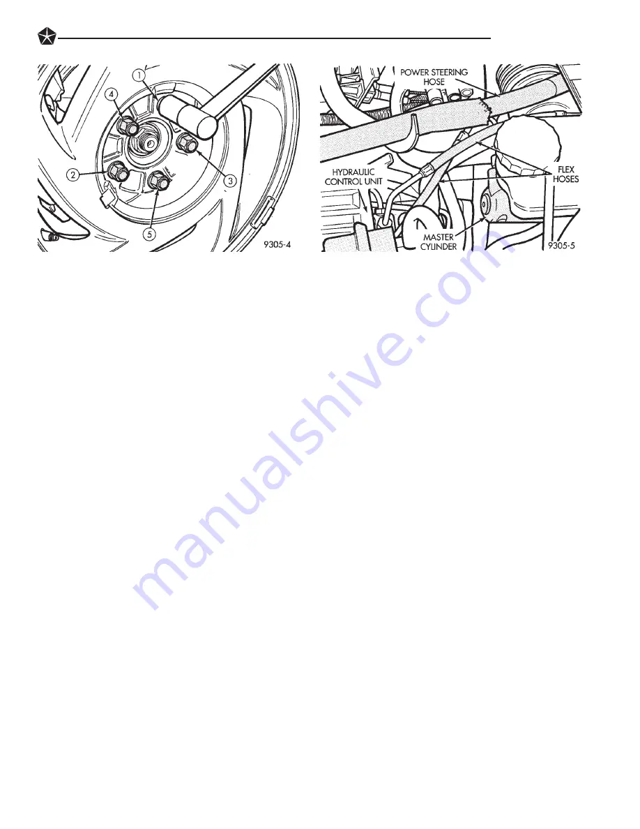
The L.H. platform vehicles equipped with Anti-Lock
brakes, uses flexible hose to connect the master cylin-
der to the hydraulic control unit (HCU) (Fig. 1). These
hoses have a flexible stainless steel braid over the
brake hose and tube assemblies. These hoses also must
be inspected as noted above for any signs of damage or
deterioration.
INSTALLATION OF BRAKE HOSE
Always use factory recommended brake hose to en-
sure quality, correct length and superior fatigue life.
Care should be taken to make sure that the tube and
hose mating surfaces are clean and free from nicks and
burrs. Front and rear right and left side hoses, are
not interchangeable.
Connections should be correct and properly made.
Use new copper seal washers on all connections using
Banjo Bolts and tighten all fittings to their specified
torques.
The flexible front hydraulic brake hose should al-
ways be installed on the vehicle by first attaching
the Banjo connector to the caliper assembly. Then
attach the remaining hose end bracket to the vehicle
frame to minimize hose twisting. Then hand start the
steel brake tube fitting into the hose end fitting.
Tighten all attachment screws and tube fittings to
specified torque. The frame bracket is keyed so that it
will only fit one way.
On vehicles equipped with rear drum brakes, first
install rear brake flex hose into wheel cylinder then
attach bracket to brake support plate. Then attach
brake hose end bracket to vehicle frame to minimize
hose twisting. Then hand start the steel brake tube
fitting into the hose end fitting. Tighten all attachment
screws and tube fittings to their specified torque (See
Specifications Section) at the end of this group for the
required fitting torques.
Vehicles equipped with rear disc brakes have brake
flex hoses attached to the brake caliper on each side of
vehicle. The brake flex hose should be first attached to
the Banjo bolt at the caliper and then secured the flex
hose/bracket at the vehicle frame. Then attach the
steel brake tubing to the hose fitting. Tighten all
attachment screws and brake line tube fittings to their
specified torque (See Specifications Section) at the end
of this group for the required fitting torques.
REPAIR AND INSTALLATION OF BRAKE TUB-
ING
Only double wall 4.75mm (3/16 in.) steel tubing
should be used for replacement. L.H. platform brake
tubes are coated with a zinc alloy and aluminum
rich coating referred to as Prokote 2000. If brake
line tubing requires replacement, brake line tub-
ing with this same coating should only be used as
a service replacement. Care should be taken when
replacing brake tubing, to be sure the proper bending
and flaring tools and procedures are used, to avoid
kinking. Do not route the tubes against sharp edges,
moving components or into hot
Fig. 5 Tightening Wheel Nuts
Fig. 1 Anti-Lock Equipped Vehicle Flex Hoses
BRAKES
5 - 7
Summary of Contents for Concorde 1993
Page 4: ......
Page 7: ...LUBRICATION AND MAINTENANCE SCHEDULES LUBRICATION AND MAINTENANCE 0 3 ...
Page 22: ......
Page 24: ...Fig 1 L H Platform Front Suspension 2 2 SUSPENSION AND DRIVESHAFTS ...
Page 25: ...SUSPENSION STEERING DIAGNOSIS FRONT WHEEL DRIVE SUSPENSION AND DRIVESHAFTS 2 3 ...
Page 27: ...Fig 2 L H Platform Front Suspension SUSPENSION AND DRIVESHAFTS 2 5 ...
Page 44: ...Fig 1 Front Stabilizer Bar And Stabilizer Bar Mounting 2 22 SUSPENSION AND DRIVESHAFTS ...
Page 63: ...SUSPENSION STEERING DIAGNOSIS FRONT WHEEL DRIVE SUSPENSION AND DRIVESHAFTS 2 41 ...
Page 75: ...Fig 1 L H Platform Fully Independent Rear Suspension SUSPENSION AND DRIVESHAFTS 2 53 ...
Page 92: ...SPECIFICATIONS ALIGNMENT SPECIFICATIONS AT CURB HEIGHT 2 70 SUSPENSION AND DRIVESHAFTS ...
Page 94: ......
Page 97: ...Fig 3 Proper Nut Thread Size And Tube Routing ABS Equipped BRAKES 5 3 ...
Page 105: ...BRAKE SYSTEM DIAGNOSTICS BRAKES 5 11 ...
Page 106: ...BRAKE SYSTEM DIAGNOSTICS 5 12 BRAKES ...
Page 107: ...BRAKE SYSTEM DIAGNOSTICS BRAKE SYSTEM DIAGNOSTICS BRAKES 5 13 ...
Page 145: ...FIG 2 PARKING BRAKE CABLE ROUTING BRAKES 5 51 ...
Page 198: ...BRAKE ACTUATION SYSTEM TIGHTENING REFERENCE 5 104 ANTI LOCK BRAKE SYSTEM ...
Page 200: ...COOLING SYSTEM DIAGNOSIS 7 2 COOLING SYSTEM ...
Page 201: ...COOLING SYSTEM DIAGNOSIS COOLING SYSTEM 7 3 ...
Page 202: ...COOLING SYSTEM DIAGNOSIS 7 4 COOLING SYSTEM ...
Page 203: ...COOLING SYSTEM DIAGNOSIS COOLING SYSTEM 7 5 ...
Page 204: ...COOLING SYSTEM DIAGNOSIS 7 6 COOLING SYSTEM ...
Page 205: ...COOLING SYSTEM DIAGNOSIS COOLING SYSTEM 7 7 ...
Page 220: ...SPECIFICATIONS TORQUE COOLING SYSTEM CAPACITY 7 22 COOLING SYSTEM ...
Page 225: ...Fig 7 Battery Diagnostics BATTERY STARTING CHARGING SYSTEMS DIAGNOSTICS 8A 5 ...
Page 236: ...Fig 14 Starter Relay Tests 8A 16 BATTERY STARTING CHARGING SYSTEMS DIAGNOSTICS ...
Page 239: ...Fig 1 Charging Diagnostics BATTERY STARTING CHARGING SYSTEMS DIAGNOSTICS 8A 19 ...
Page 242: ...Fig 6 Generator Fault Codes 8A 22 BATTERY STARTING CHARGING SYSTEMS DIAGNOSTICS ...
Page 243: ...Fig 7 Check For Inadequate Low Charging BATTERY STARTING CHARGING SYSTEMS DIAGNOSTICS 8A 23 ...
Page 244: ...Fig 8 Check For Overcharging 8A 24 BATTERY STARTING CHARGING SYSTEMS DIAGNOSTICS ...
Page 258: ......
Page 282: ......
Page 291: ...Fig 25 Instrument Panel Breakdown INSTRUMENT PANEL AND GAUGES 8E 9 ...
Page 292: ...Fig 26 Instrument Panel Breakdown 207 8E 10 INSTRUMENT PANEL AND GAUGES ...
Page 296: ......
Page 298: ...Fig 1 Radio Diagnosis 8F 2 AUDIO SYSTEM ...
Page 299: ...Fig 2 Radio Connector Circuits AUDIO SYSTEM 8F 3 ...
Page 306: ......
Page 308: ...Fig 2 Horn Diagnosis 8G 2 HORNS ...
Page 310: ......
Page 313: ...Fig 4 System Diagnosis SPEED CONTROL SYSTEM 8H 3 ...
Page 314: ...Fig 5 System Diagnosis Continued 8H 4 SPEED CONTROL SYSTEM ...
Page 320: ......
Page 324: ......
Page 327: ...Fig 5 Wiper Motor Runs Diagnosis WINDSHIELD WIPER AND WASHER SYSTEMS 8K 3 ...
Page 328: ...Fig 6 Wiper Motor Will Not Run Diagnosis 8K 4 WINDSHIELD WIPER AND WASHER SYSTEMS ...
Page 350: ......
Page 360: ......
Page 364: ......
Page 370: ......
Page 374: ......
Page 382: ......
Page 388: ...ENGINE DIAGNOSIS PERFORMANCE ENGINE 9 5 ...
Page 389: ...ENGINE DIAGNOSIS MECHANICAL 9 6 ENGINE ...
Page 416: ...ENGINE SPECIFICATIONS 3 3L ENGINE 9 33 ...
Page 417: ...ENGINE SPECIFICATIONS CONT 9 34 3 3L ENGINE ...
Page 418: ...ENGINE SPECIFICATIONS CONT 3 3L ENGINE 9 35 ...
Page 419: ...ENGINE SPECIFICATIONS CONT 9 36 3 3L ENGINE ...
Page 420: ...TORQUE 3 3L ENGINE 9 37 ...
Page 450: ...ENGINE SPECIFICATIONS 3 5L ENGINE 9 67 ...
Page 451: ...ENGINE SPECIFICATIONS CONT 9 68 3 5L ENGINE ...
Page 452: ...ENGINE SPECIFICATIONS CONT TORQUE 3 5L ENGINE 9 69 ...
Page 453: ......
Page 456: ...EXHAUST SYSTEM DIAGNOSIS EXHAUST SYSTEM AND INTAKE MANIFOLD 11 3 ...
Page 467: ......
Page 470: ...EXHAUST SYSTEM DIAGNOSIS EXHAUST SYSTEM AND INTAKE MANIFOLD 11 3 ...
Page 481: ......
Page 485: ...Fig 6 Engine Compartment Side View 13 4 FRAME AND BUMPERS ...
Page 486: ...Fig 7 Forward Frame Section and Engine Cradle FRAME AND BUMPERS 13 5 ...
Page 487: ...Fig 8 Rear Frame Section 13 6 FRAME AND BUMPERS ...
Page 491: ...Fig 6 Engine Compartment Side View 13 4 FRAME AND BUMPERS ...
Page 492: ...Fig 7 Forward Frame Section and Engine Cradle FRAME AND BUMPERS 13 5 ...
Page 493: ...Fig 8 Rear Frame Section 13 6 FRAME AND BUMPERS ...
Page 507: ...Fig 37 Chassis Fuel Tubes 14 14 FUEL SYSTEMS ...
Page 534: ...3 3L FUEL INJECTOR DIAGNOSIS FUEL SYSTEMS 14 41 ...
Page 535: ...3 5L FUEL INJECTOR DIAGNOSIS 14 42 FUEL SYSTEMS ...
Page 544: ...POWERTRAIN CONTROL MODULE 60 WAY CONNECTOR FUEL SYSTEMS 14 51 ...
Page 545: ...DIAGNOSTIC TROUBLE CODE DESCRIPTION 14 52 FUEL SYSTEMS ...
Page 546: ...DIAGNOSTIC TROUBLE CODE DESCRIPTION CONTINUED FUEL SYSTEMS 14 53 ...
Page 547: ...DIAGNOSTIC TROUBLE CODE DESCRIPTION CONTINUED 14 54 FUEL SYSTEMS ...
Page 567: ...STEERING COMPONENTS SERVICE DIAGNOSIS POWER STEERING SERVICE DIAGNOSIS 19 2 STEERING ...
Page 568: ...POWER STEERING SERVICE DIAGNOSIS STEERING 19 3 ...
Page 569: ...POWER STEERING SERVICE DIAGNOSIS 19 4 STEERING ...
Page 570: ...POWER STEERING SERVICE DIAGNOSIS STEERING 19 5 ...
Page 571: ...POWER STEERING SERVICE DIAGNOSIS 19 6 STEERING ...
Page 572: ...POWER STEERING SERVICE DIAGNOSIS STEERING 19 7 ...
Page 591: ...Fig 1 L H Platform Saginaw Tilt Steering Column 19 26 STEERING ...
Page 604: ...DIAGNOSIS GUIDE VEHICLE WILL NOT MOVE TRANSAXLE 21 5 ...
Page 605: ...DIAGNOSIS GUIDE FLUID LEAKS 21 6 TRANSAXLE ...
Page 606: ...DIAGNOSTIC TROUBLE CODE CHART A TRANSAXLE 21 7 ...
Page 607: ...DIAGNOSIS CHART B 21 8 TRANSAXLE ...
Page 682: ...DIAGNOSTIC TROUBLE CODE 11 DIAGNOSTIC TROUBLE CODE 12 TRANSAXLE 21 83 ...
Page 683: ...DIAGNOSTIC TROUBLE CODE 13 DIAGNOSTIC TROUBLE CODE 14 21 84 TRANSAXLE ...
Page 684: ...DIAGNOSTIC TROUBLE CODE 15 DIAGNOSTIC TROUBLE CODE 16 TRANSAXLE 21 85 ...
Page 685: ...DIAGNOSTIC TROUBLE CODE 17 DIAGNOSTIC TROUBLE CODE 18 21 86 TRANSAXLE ...
Page 686: ...DIAGNOSTIC TROUBLE CODE 19 DIAGNOSTIC TROUBLE CODE 20 TRANSAXLE 21 87 ...
Page 687: ...DIAGNOSTIC TROUBLE CODE 21 27 21 88 TRANSAXLE ...
Page 689: ...DIAGNOSTIC TROUBLE CODE 29 DIAGNOSTIC TROUBLE CODE 31 32 21 90 TRANSAXLE ...
Page 690: ...DIAGNOSTIC TROUBLE CODE 36 DIAGNOSTIC TROUBLE CODE 37 TRANSAXLE 21 91 ...
Page 691: ...DIAGNOSTIC TROUBLE CODE 38 21 92 TRANSAXLE ...
Page 692: ...DIAGNOSTIC TROUBLE CODE 41 44 TRANSAXLE 21 93 ...
Page 693: ...DIAGNOSTIC TROUBLE CODE 45 DIAGNOSTIC TROUBLE CODE 46 21 94 TRANSAXLE ...
Page 695: ...DIAGNOSTIC TROUBLE CODE 50 58 21 96 TRANSAXLE ...
Page 696: ...DIAGNOSTIC TROUBLE CODE 60 62 TRANSAXLE 21 97 ...
Page 697: ...42LE HYDRAULIC SCHEMATICS 21 98 TRANSAXLE ...
Page 698: ... TRANSAXLE 21 99 ...
Page 699: ...21 100 TRANSAXLE ...
Page 700: ...TRANSAXLE 21 101 ...
Page 701: ...21 102 TRANSAXLE ...
Page 702: ...TRANSAXLE 21 103 ...
Page 703: ...21 104 TRANSAXLE ...
Page 704: ...TRANSAXLE 21 105 ...
Page 705: ...21 106 TRANSAXLE ...
Page 706: ...TRANSAXLE 21 107 ...
Page 707: ...21 108 TRANSAXLE ...
Page 708: ...TRANSAXLE 21 109 ...
Page 709: ...21 110 TRANSAXLE ...
Page 710: ...42LE SPECIFICATIONS 42LE FOUR SPEED AUTOMATIC TRANSAXLE TRANSAXLE 21 111 ...
Page 712: ...MASTER SHIM CHART TRANSAXLE 21 113 ...
Page 713: ......
Page 717: ...Fig 4 Tire Wear Patterns 22 4 WHEELS TIRES ...
Page 718: ...LEAD CORRECTION CHART WHEELS TIRES 22 5 ...
Page 765: ...Fig 5 Charge Determination Graph 24 6 HEATING AND AIR CONDITIONING ...
Page 781: ...DRB II SCAN TOOL FLOW CHART MANUAL ATC 24 22 HEATING AND AIR CONDITIONING ...
Page 782: ...DRB II SCAN TOOL MENU BODY SECTION CLIMATE CONTROL ITEMS HEATING AND AIR CONDITIONING 24 23 ...
Page 783: ...DRB II SCAN TOOL FLOW CHART SYSTEM TESTS 24 24 HEATING AND AIR CONDITIONING ...
Page 786: ...ENGINE VACUUM SCHEMATIC 3 3L ENGINE EMISSION CONTROL SYSTEMS 25 3 ...
Page 787: ...ENGINE VACUUM SCHEMATIC 2 5L ENGINE 25 4 EMISSION CONTROL SYSTEMS ...
Page 796: ...EGR DIAGNOSIS CHART 3 3L ENGINE EMISSION CONTROL SYSTEMS 25 13 ...
Page 804: ...CONVERSION TABLES INTRODUCTION 5 ...
Page 805: ...CONVERSION TABLES INTERNATIONAL CONTROL AND DISPLAY SYMBOLS 6 INTRODUCTION ...
Page 810: ... 520 QVWDOODWLRQ QG 2SHUDWLRQ QVWUXFWLRQ RRNOHW ...