2. Press and release the EVIC button several times until
the EVIC displays the Personal Settings (Customer Pro-
grammable Features) menu.
3. Press and release the EVIC button several times until
“Calibrate Compass (Yes)” is displayed. A long (longer
than two seconds) EVIC button Press will place the
Compass in calibration mode.
4. The “CAL” indicator will come on continuously in the
EVIC display to indicate that the compass is now in the
calibration mode and that the vehicle can now be driven
to calibrate. Press the EVIC button from the
9
Calibrate
Compass (Yes)
9
screen will exit the EVIC Customer
Programmable features, and return it to its normal oper-
ating mode).
5. Drive the vehicle slowly, under 5 mph (8 km/h),
completing one or more circles (in an area free from large
metal or metallic objects) until the “CAL” indicator turns
off. The compass will now function normally.
Compass Variance
Compass Variance is the difference between magnetic
North and Geographic North. In some areas of the
country, the difference between magnetic and geographic
North is great enough to introduce some compass error.
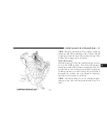
In order to ensure compass accuracy, the compass vari-
ance should be properly set according to the variance
zone map for the vehicle’s current location. The compass
in your vehicle will now automatically compensate for
this difference.
NOTE:
Magnetic materials such as a laptop computer,
cell phone, and PDA’s (anything with a battery), should
be kept away from the top of the instrument panel. This
is where the compass sensor is located.
248
UNDERSTANDING YOUR INSTRUMENT PANEL
Summary of Contents for 2008 PT Cruiser
Page 4: ......
Page 7: ...INTRODUCTION 5 1 ...
Page 10: ......
Page 120: ......
Page 161: ...UNDERSTANDING THE FEATURES OF YOUR VEHICLE 159 3 ...
Page 162: ...160 UNDERSTANDING THE FEATURES OF YOUR VEHICLE ...
Page 163: ...UNDERSTANDING THE FEATURES OF YOUR VEHICLE 161 3 ...
Page 225: ...INSTRUMENT CLUSTER BASE UNDERSTANDING YOUR INSTRUMENT PANEL 223 4 ...
Page 226: ...INSTRUMENT CLUSTER PREMIUM 224 UNDERSTANDING YOUR INSTRUMENT PANEL ...
Page 227: ...INSTRUMENT CLUSTER TURBO UNDERSTANDING YOUR INSTRUMENT PANEL 225 4 ...
Page 285: ...Operating Tips Control Settings Chart UNDERSTANDING YOUR INSTRUMENT PANEL 283 4 ...
Page 288: ......
Page 322: ...320 STARTING AND OPERATING ...
Page 380: ...2 4L TURBO ENGINE COMPARTMENT 378 MAINTAINING YOUR VEHICLE ...
Page 381: ...2 4L ENGINE COMPARTMENT MAINTAINING YOUR VEHICLE 379 7 ...
Page 434: ......
Page 460: ......
Page 471: ...INDEX 10 ...

