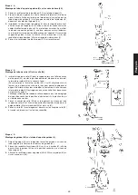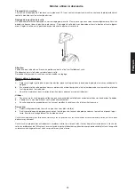
20
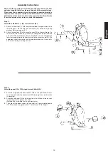
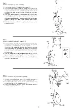
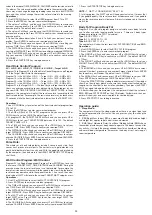
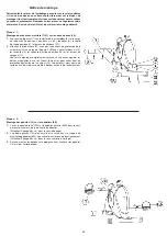
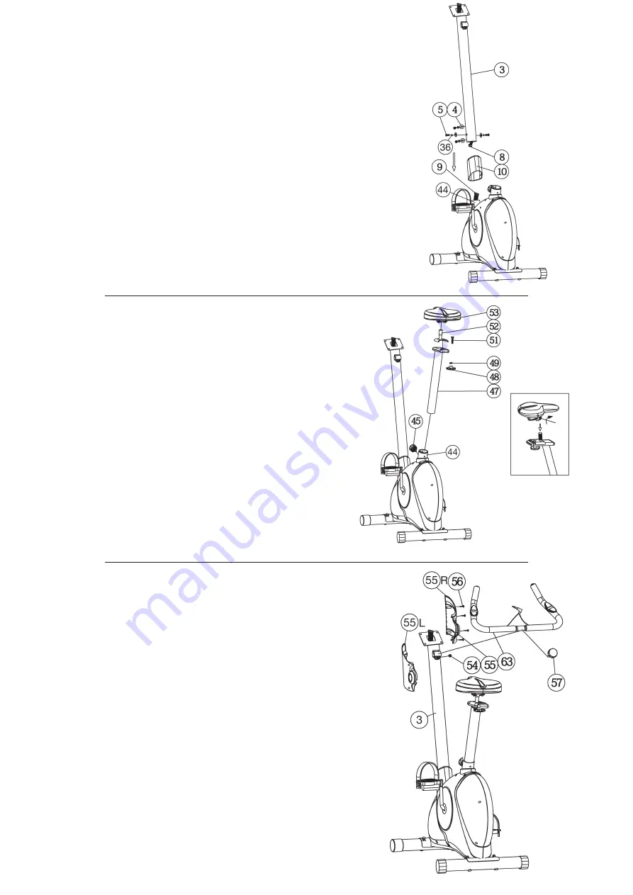
Step 3:
Attach the front post (3) at main frame (44).
1.
Push the support cover (10) onto handlebar support (3).
2.
Hold the handlebar support (3) with the computer cable (8) against the
main frame holder and connect the plug for the computer cable (8)
coming out of the bottom of the handlebar support (3) of the computer
with the matching plug for the motor cable (9) coming out of the main
frame (44).
3.
Place the handlebar support (3) in the locator provided for it in the main
frame (44). Ensure that the cable connections made in step 3 are not
squashed. When putting the steering tube in place, push the former
slowly down into the locator in the main frame. Screw the handlebar
support (3) onto the base frame (44) with the screws (5), spring washers
(36) and washers (4).
4.
Push the plastic cover (10) into the right position to cover up the
connection screws.
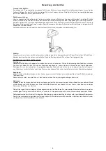
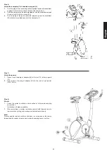
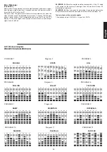
Step 4:
Attach the saddle (53) and saddle support (47).
1.
Push the saddle support tube (47) into the matching locator in the main
frame (44), set it at the desired position and lock it by inserting the bolt
with the quick release (45) in place and doing it up tight.
(The setting of the saddle support can be adjusted easily as desired
later through turning and pulling the quick release (45).) Furthermore,
you must ensure when setting this desired position that the seat pillar is
not pulled out of the main frame further than the highest setting position,
which is marked.
2.
Place the saddle slide (52) into the holder of saddle post (47), set it at
the desired position and screw it onto the saddle support (47) by screw
(51) washer (49) and star grip nut (48).
3.
Push the saddle (53) with saddle bracket into the saddle slide (52) and
tight it up in desired position.
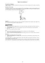
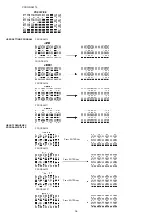
Step 5:
Attach the handlebar (63) at handlebar support (3).
1.
Guide the preassembled handlebar unit (63) through the upper part of
the handlebar post (3) and close the bracket of handlebar holder.
2.
Screw the handlebar (63) in desired position at the handlebar post (3)
with distance tube (54) and handlebar screw (57).
3.
Attach the handlebar covers (55L+55R) at the handlebar holder of
handlebar support (3) with screws (56).
Summary of Contents for 1105
Page 3: ...3 Deutsch ...
Page 13: ...13 Deutsch BENUTZER PROGRAMME HERZFREQUENZ PROGRAMMPROFILE ...
Page 71: ...71 ...

