background image

2. Disconnect and reconnect the cable for the affected formatter board on the high-speed

imaging processing board (HIP) board.
Make sure you hear a clicking sound when you connect the cable. For example, disconnect and
reconnect the red cable.

3. Re-install the top cover.
4. Turn on the projector and look at the error messages displayed in the display panel.

If the Formatter Fault error is still displayed, continue to the next step.

If the error is not reported, 4K40-RGB is working as expected. Disregard the remaining
steps.

5. Remove the top cover.
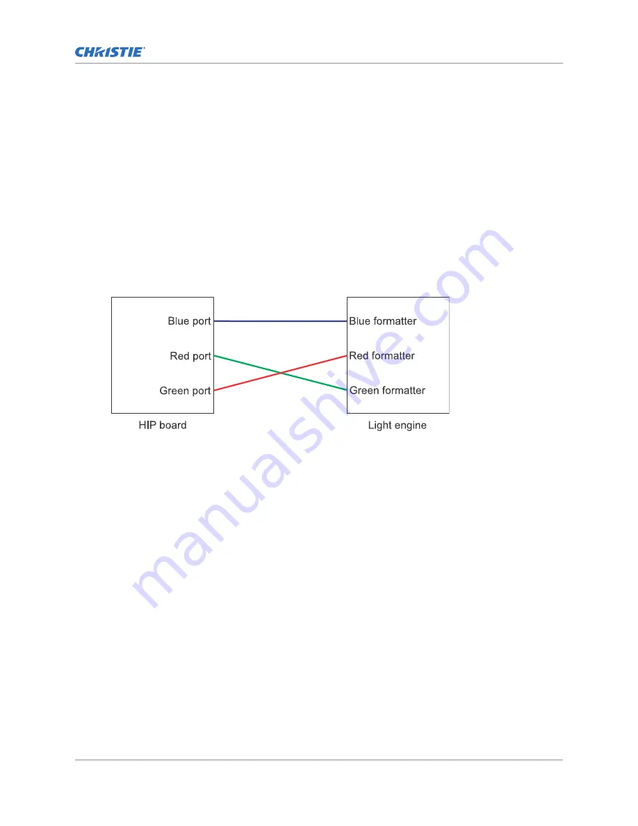
6. From the HIP board side, swap the HIP port cables from the formatter board having issues with

one of the two other formatter board cables.
For example, swap the red formatter cable with the green formatter cable from the HIP side
ports.

7. Re-install the top cover.
8. Turn on the projector and look at the error messages displayed in the display panel.

If the Formatter Fault error stays with the initial board, the issue is with the HIP board.
Change the cables to their original positions and confirm the error still persists. If it does,
replace the HIP.

If the Formatter Fault error moved from the one formatter board to the other (for
example, moved from the red formatter board to the green formatter board), the issue is
with the cables or the formatter board. Proceed to the next step.

9. Remove the top cover.
10. On the light engine side, swap the same formatter cables you swapped in step 6 on the HIP

board side.
For example, swap the red cable for the green cable. For more information on the light engine,
see the 4K40-RGB Service Guide (P/N: 020-102960-XX).

4K40-RGB troubleshooting

4K40-RGB Technical Reference–Troubleshooting

18

020-103239-01 Rev. 1 (09-2020)

Copyright 

©

 2020 Christie Digital Systems USA, Inc. All rights reserved.

Summary of Contents for Mirage 4K40-RGB

Page 1: ...Technical Reference 020 103239 01 4K40 RGB Troubleshooting...

Page 2: ...ed modified or approved by Christie for such use g Except where the product is designed for outdoor use problems or damage caused by use of the product outdoors unless such product is protected from p...

Page 3: ...greyed out 12 Color on the screen is not stable 12 Colors on the screen not accurate 13 Blemishes appearing on the screen 13 Projector brightness lower than expected 14 Projector noisier than expecte...

Page 4: ...short circuit current capacity that may cause severe burns and electrical arcing Related information Use this guide in conjunction with the 4K40 RGB Service User and Status System guides available on...

Page 5: ...rmatted using the FAT 32 file system 2 Select MENU Admin Interrogator 3 Select Run If on the projector the interrogator file is stored at the root directory on the USB flash drive If running 4K40 RGB...

Page 6: ...display panel Enter key Resolution 1 Check the breaker switch is on or the breaker is not damaged If the breaker switch is not on turn it on Check the line cord for damage and proper connection If the...

Page 7: ...wer is coming into the power supply Ensure a certified electrician checks the line voltage and supply from the wall Solid red Over Loaded A potential short in the output of the power supply occurred I...

Page 8: ...two LEDs should be blinking If not blinking ensure the harness J30 between the housekeeping board and card cage is properly seated and connected If the display panel is on it indicates a functioning c...

Page 9: ...roceed to step 3 Solid orange DC Output OK in remote control mode Check the communication CN2 harness into the power supply is fully seated and connected Slow blinking green Output Not Enabled There i...

Page 10: ...10 from the housekeeping board to the 48VDC LVPS Communications harness J112 from the housekeeping board to the 12 VDC LVPS Power harness J111 from the LCDD to the 48 VDC LVPS Power harness J113 from...

Page 11: ...ient temperature provides maximum power however any deviation from the optimal temperature can limit the power which is reflected on the red laser slider Some configurations may not reach 100 but the...

Page 12: ...t Output Settings functions when using LiteLOC refer to the RGB sliders greyed out on page 11 topic The color sensor board CSBD has not been calibrated for LiteLOC version 2 0 Resolution 1 Ensure Lite...

Page 13: ...correction modes were not selected to match the content playing on the screen The precise color chromaticity was either set up wrong or not enabled Resolution 1 Disable the existing color settings by...

Page 14: ...ave occurred due to an optical misalignment of the optical coupling mirror that shows up as a brightness drop on the screen If the DMDs overfill up to 10 loss of brightness can occur Resolution 1 Use...

Page 15: ...emperature When predicting watch for the following Too low the LiteLOC status item display a warning Too high available red laser power is limited Christie assumes the projector is operating in a high...

Page 16: ...ature sensors have not failed or been disconnected LOS Dewpoint Approaching Limit warning Received a LOS Dewpoint Approaching Limit warning during calibration Details The projector is reacting to humi...

Page 17: ...etected warning to focus on the HVCS or LVCS board affected at that slot Reconnect or replace the harnessing going to that board b If the warning persists swap in a different HVCS board and if the war...

Page 18: ...e install the top cover 8 Turn on the projector and look at the error messages displayed in the display panel If the Formatter Fault error stays with the initial board the issue is with the HIP board...

Page 19: ...ample the green board the issue is with the initial cable for example the red cable Replace the affected cable If the original Formatter Fault is still reported the issue is with the formatter board R...

Page 20: ...6877 8737 Africa ph 27 0 11 510 0094 Korea Seoul ph 82 2 702 1601 Japan Tokyo ph 81 3 3599 7481 India ph 91 080 6708 9999 Germany ph 49 0 221 99512 0 France ph 33 0 1 41 21 44 04 Russia ph 36 0 1 47 4...

Page 21: ......

Reviews: