background image

46

APPENDIX

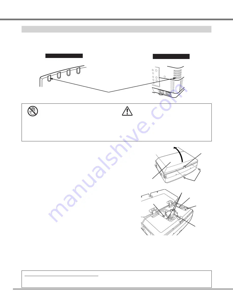
Check number of lamp to be replaced on Lamp Status Display.

Remove two screws on Lamp Cover and press button to open
Lamp Cover.  (See right figure.)

1

3

Loosen two screws and pull out Lamp Assembly to be replaced
by grasping handle.

4

Turn off a projector and disconnect AC Power Cord.  Allow a
projector to cool down for at least 45 minutes.

2

Replace Lamp Assembly with a new one and tighten two screws.
Make sure Lamp is set properly

6

Follow these steps to replace lamp assembly.

Replace Lamp Cover and tighten two screws. 

5

7

8

Connect AC Power Cord to a projector and turn a projector on.

Reset Lamp Replacement Counter. (Refer to section "Lamp
Counter Reset" on page 42.)

NOTE :

Do not reset LAMP REPLACEMENT COUNTER when
lamp is not replaced.

BUTTON

SCREWS

LAMP
COVER

SCREWS

Make sure which number of lamp needs to be
replaced on Lamp Status Display.
Figure shows case of replacing LAMP 2.

LAMP 1

LAMP 2

LAMP 3

LAMP 4

CAUTION : DO NOT OPERATE A PROJECTOR WHILE ANY OF LAMPS IS REMOVED. IT MAY
RESULT IN MALFUNCTIONS, FIRE HAZARD, OR OTHER ACCIDENTS.

NOTES ON LAMP REPLACEMENT

To maintain quality of picture (better balance of color and brightness in entire screen), we recommend replacing
all 4 lamps at a time. 

LAMP REPLACEMENT

When the life of the Projection Lamp of this projector draws to an end,
the LAMP REPLACE indicator lights yellow.  If this indicator lights
yellow, replace the projection lamp with a new one promptly.

For continued safety, replace with a lamp assembly of
the same type.
Do not drop a lamp assembly or touch a glass bulb! The
glass can shatter and may cause injury.

Allow a projector to cool, for at least 45 minutes before
you open Lamp Cover.  The inside of a projector can
become very hot.

REAR INDICATORS

CAUTION

READY

LAMP

LAMP

REPLACE

WARNING

TEMP.

WARNING

TEMP.

READ

Y

LAMP

REPLA

CE

LAMP

FRONT INDICATORS

LAMP REPLACE
INDICATOR

Summary of Contents for 38-MX3001-01

Page 1: ...User s Manual Projection lens is optional 38 MX3001 01 MODEL...

Page 2: ...UCE THE RISK OF FIRE OR ELECTRIC SHOCK DO NOT EXPOSE THIS APPLIANCE TO RAIN OR MOISTURE This projector produces intense light from the projection lens Do not stare directly into the lens Eye damage co...

Page 3: ...abinet slots as they may touch dangerous voltage points or short out parts that could result in a fire or electric shock Never spill liquid of any kind on the projector This projector should be operat...

Page 4: ...with the limits for a Class A digital device pursuant to Part 15 of FCC Rules These limits are designed to provide reasonable protection against harmful interference when the equipment is operated in...

Page 5: ...T 32 IMAGE LEVEL ADJUSTMENT 33 PICTURE SCREEN ADJUSTMENT 34 SELECTING INPUT SOURCE 35 SELECTING VIDEO SYSTEM 36 PICTURE IMAGE ADJUSTMENT 37 IMAGE LEVEL SELECT 37 IMAGE LEVEL ADJUSTMENT 38 PICTURE SCRE...

Page 6: ...a projector detects signal interruption and any button is not pressed over 5 minutes Projection Lamp is automatically turned on again when a projector detects signal or any operation button is presse...

Page 7: ...operating power of Cooling Fans FRONT OF CABINET LAMP COVER ADJUSTABLE FEET This projector is equipped with cooling fans for protection from overheating Pay attention to following to ensure proper ven...

Page 8: ...nect a projector with peripheral equipment before turning a projector on Refer to pages 12 15 for connection CONNECTING AC POWER CORD Connect AC Power Cord supplied to a projector AC outlet must be ne...

Page 9: ...LENS SHIFT ADJUSTMENT MOVED UP OR DOWN MOVED LEFT OR RIGHT Use LENS SHIFT button and POINT UP DOWN button to move image up or down Refer to page 23 Use LENS SHIFT button and POINT LEFT RIGHT button to...

Page 10: ...ector Moving it unproperly may result in damage of cabinet or person s injury Replace lens cover and retract feet to pre vent damage to lens and cabinet 1 2 3 Pull up lock buttons on each side of carr...

Page 11: ...it Plug into Socket 3 4 ANALOG RGB R Pr G Y B Pb H HV V CONTROL PORT DVI INPUT 1 R C JACK USB RESET MONO MONO MONO MONO MONO CONTROL PORT AUDIO CONTROL PORT S VIDEO VIDEO Y C INPUT 2 INPUT 3 INPUT 4 A...

Page 12: ...L PORT CONNECTORS AUDIO INPUT JACKS 5 BNC INPUT JACKS S VIDEO INPUT JACK Connect component video output Cr Y Cb or Pr Y Pb from video equipment to R Pr G Y and B Pb jacks or connect computer output 5...

Page 13: ...RGB R Pr G Y B Pb H HV V CONTROL PORT DVI INPUT 1 R C JACK USB RESET MONO MONO MONO MONO MONO CONTROL PORT AUDIO CONTROL PORT S VIDEO VIDEO Y C INPUT 2 INPUT 3 INPUT 4 AUDIO AUDIO AUDIO SERIAL PORT I...

Page 14: ...trol Cable for PS 2 port Serial port or ADB port MAC VGA Adapter DVI VGA Adapter DVI Cable BNC Cable BNC x 5 Audio Cables RCA x 2 Control Cable for PS 2 Port Control Cable for ADB Port Audio Cable ste...

Page 15: ...ut Cables used for connection Video Cable BNC x 1 BNC x 2 or BNC x 3 S VIDEO Cable Audio Cable RCA x 2 Cables are not supplied with this projector NOTE When connecting cable power cords of both a proj...

Page 16: ...Used to select an item or adjust value in MENU It is also used to pan image in DIGITAL ZOOM mode P34 Used to execute item selected It is also used to expand image in DIGITAL ZOOM mode P34 Used to turn...

Page 17: ...n a projector is turned on And bright when a projector is in stand by mode INDICATORS WARNING TEMP INDICATOR This indicator flashes red when internal projector temperature is too high P43 WARNING TEMP...

Page 18: ...xposure Laser Light Window These caution labels are put on remote control LASER POINTER FUNCTION Used to select input source either INPUT 1 or INPUT 2 P26 Used to execute item selected or to expand or...

Page 19: ...te Control Unit toward projector Receiver Window whenever pressing any button Maximum operating range for Remote Control Unit is about 16 4 5m and 60 in front and rear of a projector 16 4 5 m 60 16 4...

Page 20: ...ages to operate each adjustment on ON SCREEN MENU 2 MOVING POINTER 3 SELECT ITEM Move pointer see below or adjust value of item by pressing POINT button s on Side Control or on Remote Control Unit Sel...

Page 21: ...T MENU Used to adjust picture image Contrast Brightness Color Tint Color Temp White balance R G B Sharpness Gamma Noise Reduction Progressive Refer to P38 39 FOR VIDEO SOURCE Press MENU BUTTON while c...

Page 22: ...ent function is ON projector detects signal interruption and turns off Projection Lamp automatically Refer to Power Management on pages 40 and 41 Press POWER ON OFF button again to turn off projector...

Page 23: ...SCREEN Message disappears after 4 seconds Message disappears after 4 seconds Zoom Focus ZOOM ADJUSTMENT FOCUS ADJUSTMENT 1 Press ZOOM button on Side Control or on Remote Control Unit Message Zoom is d...

Page 24: ...e Control Unit to black out a image To restore to normal press NO SHOW button again or press any other button except POINT SELECT RIGHT CLICK LASER button NO SHOW FUNCTION Message disappears after 4 s...

Page 25: ...og box display is changed to On and sound is cut off To restore sound to its previous level press POINT LEFT RIGHT button s again Press POINT DOWN button to move a red frame pointer to item that you w...

Page 26: ...ION DIRECT OPERATION Select INPUT source by pressing INPUT 1 2 and INPUT 3 4 buttons on Side Control or on Remote Control Unit Press MENU button and ON SCREEN MENU will appear Press POINT LEFT RIGHT b...

Page 27: ...e connection of computer and a projector is set correctly Refer to TROUBLESHOOTING on page 48 Auto PC SYSTEM Menu icon Displays system being selected PC SYSTEM MENU SELECT COMPUTER SYSTEM MANUALLY PC...

Page 28: ...0 SXGA 7 1280 x 1024 63 34 59 98 SXGA 8 1280 x 1024 63 74 60 01 SXGA 11 1152 x 900 71 69 67 19 SXGA 12 1152 x 900 81 13 76 107 SXGA 13 1280 x 1024 Interlace 63 98 60 02 SXGA 14 1280 x 1024 Interlace 6...

Page 29: ...pointer to AUTO PC Adj icon and press SELECT button PC ADJUST MENU Auto PC Adj PC ADJUST Menu icon Store adjustment parameters Adjustment parameters from Auto PC Adjustment can be memorized in this p...

Page 30: ...pointer to PC ADJUST Menu icon 1 2 Press POINT DOWN button to move a red frame pointer to item that you want to adjust and then press SELECT button Adjustment dialog box will appear Press POINT LEFT R...

Page 31: ...screen Reset Store Closes PC ADJUST MENU Quit Other icons operates as follows 3 To store adjustment parameters move a red frame pointer to Store icon and then press SELECT button Move a red arrow poi...

Page 32: ...ENU Normal picture level preset on this projector Standard Picture level with improved halftone for graphics Real User preset picture adjustment in IMAGE ADJUST Menu P33 IMAGE 1 4 IMAGE SELECT Menu ic...

Page 33: ...ant to set and then press SELECT button Store icon Press SELECT button at this icon to store adjustment IMAGE ADJUST Menu icon Press POINT LEFT button to lighten red tone and POINT RIGHT button to dee...

Page 34: ...TE Picture screen adjustment cannot be operated when 720p HDTV 1035i HDTV 1080i50 HDTV or 1080i60 HDTV is selected on PC SYSTEM Menu P27 True and Digital zoom cannot be operated when RGB 480p or 575p...

Page 35: ...to those equipment select a type of Video source in SOURCE SELECT VIDEO Menu WHEN SELECT INPUT 3 AV TERMINAL Press MENU button and ON SCREEN MENU will appear Press POINT LEFT RIGHT button to move a r...

Page 36: ...atically detects incoming Video signal and adjusts itself to optimize its performance When Video System is 1035i 1080i50 or 1080i60 select system manually first If projector can not reproduce proper v...

Page 37: ...re level preset on this projector Standard Picture level adjusted for picture with fine tone Cinema User preset picture adjustment in IMAGE ADJUST Menu P39 IMAGE 1 4 IMAGE SELECT Menu icon IMAGE LEVEL...

Page 38: ...roper color From 0 to 63 Color Tint Press POINT LEFT button to soften image and POINT RIGHT button to sharpen image From 0 to 15 Sharpness Press POINT LEFT button to lighten red tone and POINT RIGHT b...

Page 39: ...i60 is selected on AV SYSTEM Menu P36 Move a red frame to function and press SELECT button SCREEN MENU SCREEN Menu icon Provides image at a wide screen ratio of 16 9 Wide Provides image at a normal vi...

Page 40: ...is selectable from among English German French Italian Spanish Portuguese Dutch Swedish Russian Chinese Korean and Japanese Display This function decides whether to display On Screen Displays On show...

Page 41: ...ching function prevents remote control operation mixture jam when operating several projectors or video equipment together When operating projector in Code 2 both projector and Remote Control Unit mus...

Page 42: ...ator stops lighting Turn projector on press MENU button and ON SCREEN MENU will appear Press POINT LEFT RIGHT button s to move a red frame pointer to SETTING Menu icon 1 Press POINT DOWN button to mov...

Page 43: ...CLICK button on Wireless Remote Control Unit Used to move PC mouse pointer Pointer is moved corresponding with direction you are pressing POINT button This button has same function as left button in a...

Page 44: ...MENDATION We recommend avoiding dusty smoky environments when operating a projector Usage in these environments may cause poor image quality When using under dusty or smoky conditions dust may accumul...

Page 45: ...replace lamp LAMP REPLACE indicator lights yellow LAMP REPLACE indicator flashes yellow Projection lamp is defective or fails to be turned on Restart a projector on and make sure lamp is on If this m...

Page 46: ...replaced on Lamp Status Display Figure shows case of replacing LAMP 2 LAMP 1 LAMP 2 LAMP 3 LAMP 4 CAUTION DO NOT OPERATE A PROJECTOR WHILE ANY OF LAMPS IS REMOVED IT MAY RESULT IN MALFUNCTIONS FIRE HA...

Page 47: ...he environment or conditions in which the projector and lamp are being used IF A LAMP EXPLODES THE FOLLOWING SAFETY PRECAUTIONS SHOULD BE TAKEN If a lamp explodes disconnect the projector s AC plug fr...

Page 48: ...After pressing Power ON OFF button to OFF make sure a projector works as follows 1 LAMP indicator lights bright and READY indicator turns off 2 After 90 seconds READY indicator lights green again and...

Page 49: ...xplain difficulty We will advise you how to obtain service This symbol on the nameplate means the product is Listed by Underwriters Laboratories Inc It is designed and manufactured to meet rigid U L s...

Page 50: ...R Pr G Y B Pb H HV and V RCA Type Audio R and L and DIN 8 pin Control port Input 2 Jacks BNC Type x 2 VIDEO Y C RCA Type Audio R and L and DIN 4 pin S Video Input 3 Jacks HDB 15 pin Terminal Analog RC...

Page 51: ...8 7 6 Pin Configuration CONTROL PORT CONNECTOR CLK DATA GND GND R X D GND RTS T X D GND GND ADB GND GND PS 2 Serial ADB 1 2 3 4 5 6 7 8 DVI I TERMINAL DIGITAL ANALOG This terminal accepts only Digital...

Page 52: ...t serial port output terminal of computer to this terminal with Serial Cable not supplied Pin Configuration SERIAL PORT IN OUT TERMINAL USB PORT TERMINAL Pin Configuration Connect USB port output term...

Page 53: ...53 APPENDIX...

Page 54: ...54 APPENDIX...

Page 55: ...55 APPENDIX...

Page 56: ...236 8610 Fax 714 503 3385 Toll Free 1 800 407 7727 Toll Free 1 800 333 3816 CHRISTIE DIGITAL SYSTEMS Inc ViewPoint 200 Ashville Way Wokingham Berkshire U K RG41 2PL Telephone 44 118 977 8000 Fax 44 11...

Reviews: