background image

- 7 -

English

S–VIDEO

R–AUDIO–L

VIDEO/Y Cb/Pb    Cr/Pr

VIDEO/Y

Cb/Pb

Cr/Pr

RESET

CONTROL PORT 

AUDIO 1

AUDIO 2

ANALOG

DIGITAL(DVI-D)

INPUT 1

INPUT 2

INPUT 3

R/C JACK

G

B

R

H/V

V

(MONO)

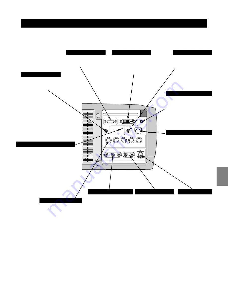
TERMINALS OF PROJECTOR

When controlling the projector
from a computer, connect the
computer to this connector
with a control cable.

Connect S-VIDEO
output from video
equipment to this
jack.

Connect an audio output
from video equipment to
these jacks.  
When the audio output is
monaural, connect it to
L (MONO) jack.

CONTROL PORT CONNECTOR

AUDIO INPUT JACKS

VIDEO INPUT JACKS

S-VIDEO INPUT JACK

Connect composite video
output from video equipment
to VIDEO/Y jack or connect
component video outputs to
VIDEO/Y, Cb/Pb and Cr/Pr
jacks.

Connect computer output
(Analog HDB 15 pin type)
to  this terminal.

INPUT TERMINAL  (ANALOG)

This projector has input and output terminals on its back for connecting computers and video equipment.  Refer to figures on
pages 12 to 14 and connect properly.

This projector uses a micro processor
to control this unit, and occasionally,
this micro processor may malfunction
and need to be reset.  This can be
done by pressing RESET button with a
pen, which will shut down and restart
unit. Do not use RESET function
excessively.

RESET BUTTON

Connect component video
output (Y, Cb, Cr or Y, Pb, Pr)
from video equipment to
VIDEO/Y, Cb/Pb and Cr/Pr
jacks or connect computer
output {5 BNC Type (Green,
Blue, Red, Horiz. Sync and
Vert. Sync.)} from computer
to G, B, R, H/V and V jacks.

5 BNC INPUT JACKS

When using Wired/Wireless
Remote Control Unit as Wired
Remote Control, Connect
Wired Remote Control Unit to
this jack with Remote Control
Cable (not supplied).

R/C JACK

Connect an audio output
(stereo) from computer to
this jack.

Connect computer output
(Digital DVI-D type) to this
terminal.
HD (HDCP Compatible) signal
can also be connected.

INPUT TERMINAL  (DIGITAL)

Connect an audio output
(stereo) from computer to
this jack.

AUDIO INPUT  1 JACK

AUDIO INPUT  2 JACK

Summary of Contents for 103-011100-01

Page 1: ...setting up the projector For detailed information about installation setup and operation of the projector refer to the owner s manual on the CD ROM READ THE SAFETY INSTRUCTIONS IN THE OWNER S MANUAL C...

Page 2: ...ling Fans FRONT OF CABINET LAMP COVER ADJUSTABLE FEET AND FEET LOCK LATCHES This projector is equipped with cooling fans for protection from overheating Pay attention to following to ensure proper ven...

Page 3: ...AC Power Cord when an appliance is not used When this projector is connected to outlet with AC Power Cord an appliance is in Stand by Mode and consumes a little electric power CONNECTING AC POWER CORD...

Page 4: ...signed to project on a flat projection surface ROOM LIGHT Brightness in a room has a great influence on picture quality It is recommended to limit ambient lighting in order to provide best image SCREE...

Page 5: ...ront of a projector and pull and undo FEET LOCK LATCHES Position and keystone distortion of image can be adjusted using Menu Operation 3 INSTALLING PROJECTOR IN PROPER POSITION Install the projector p...

Page 6: ...rt service in an unsuitable transport case This may cause damage to a projector To transport a projector through a courier or transport service consult your dealer for best way MOVING PROJECTOR Use Ca...

Page 7: ...g computers and video equipment Refer to figures on pages 12 to 14 and connect properly This projector uses a micro processor to control this unit and occasionally this micro processor may malfunction...

Page 8: ...ut CONTROL PORT AUDIO IN 1 or 2 INPUT TERMINAL ANALOG Cables used for connection Cable or adapter is not supplied with this projector Audio Cable stereo VGA Cable HDB 15 pin DVI Digital Cable for Sing...

Page 9: ...ment such as DVD player or high definition TV source Composite Video Output Component Video Output Y Cb Pb Cr Pr Component Video Output Y Cb Pb Cr Pr Y Cb Pb Cr Pr Video Cables RCA x 1 or RCA x 3 BNC...

Page 10: ...adjust value in ON SCREEN MENU They are also used to pan image in DIGITAL ZOOM mode POINT LEFT RIGHT buttons are also used as VOLUME buttons Used to execute item selected It is also used to expand com...

Page 11: ...battery is incorrectly replaced Dispose of used batteries according to batteries manufacturers instructions and local rules Pull up lid and remove it Remove battery compartment lid Slide batteries in...

Page 12: ...draws to an end Flashes yellow when the lamp cannot light up Flashes red when internal projector temperature is too high Used to select input source Used to select an item or adjust value in ON SCREEN...

Page 13: ...FT POINT BUTTONS REMOTE CONTROL UNIT ON OFF SELECT COLOR M MENU LIGHT I INPUT 2 3 SCREEN L L 1 D ZOOM NOSHOW FREEZE MUTE Z Z F F KEYS I I INPUT IMAGE SELECTION KEYSTONE FOCUS LENS ZOOM V O L U M E V O...

Page 14: ...specific users from operating the projector A PIN code consists of a four digit number Refer to PIN Code Lock function in Setting menu in the user s manual for locking operation of the projector with...

Page 15: ...r has cooled down READY Indicator lights GREEN again and you can turn projector on After cooling down completely disconnect AC Power Cord The message disappears after 4 seconds The projector cannot be...

Page 16: ......

Reviews: