background image

Section 3: Operation

J Series 1000W & 1200W Setup Guide

3-3

020-100740-02  Rev. 1  (03-2014)

Wired Remote

You can convert the remote keypad into a wired remote keypad using the cable provided with the projector. 
Connect one end into the remote and the other to the XLR connector on the input panel labeled as wired 
keypad. The wired remote is recommended when:

• The built-in keypad is inaccessible

• The lighting conditions are unsuitable for proper IR transmission 

NOTE:

 Leave the batteries in the wired remote for the laser pointer key


to work.


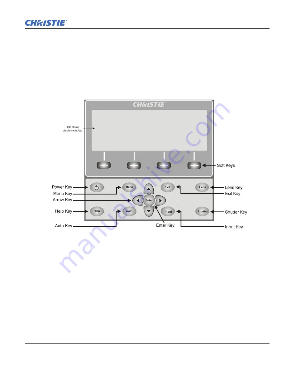
Built-in Keypad

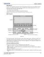
The built-in keypad has a LCD status display window which displays all states of the keypad controls. The 
LCD displays status information when the projector is powering up “Warm up: Lamp is warming up” and 
when the projector is cooling down “Cool down: Lamp is cooling down.” The display shows the state of the 
keys, menu structure, and menu items.

Overview of LED and Key States

The LED color of the keys indicates that the key is in one of these states:

Amber

, a functionality is available that will affect the displayed image of the projector

Blue

, a functionality is available that is relevant to the built-in LCD only and will not affect the displayed 

image from the projector

Off

, the key is disabled in the current context

Power Key

, used to switch from Standby mode to ON, and from ON to Standby mode; LED always remains 

Amber

F

IGURE

 3-2 

Summary of Contents for 1000W J Series

Page 1: ...J Series 1000W 1200W S e t u p G u i d e 020 100740 02 ...

Page 2: ......

Page 3: ...J Series 1000W 1200W S e t u p G u i d e 020 100740 02 ...

Page 4: ...with high quality materials and components that can be recycled and reused This symbol means that electrical and electronic equipment at their end of life should be disposed of separately from regular waste Please dispose of the product appropriately and according to local regulations In the European Union there are separate collection systems for used electrical and electronic products Please hel...

Page 5: ...ment 2 6 2 2 4 Powering Down 2 8 2 2 5 Projector Communications 2 9 3 Operation 3 1 Operating the Projector 3 1 3 1 1 Remote Keypad Commands 3 4 3 2 Navigating the Menus 3 8 3 3 Alarms 3 12 4 Maintenance 4 1 Projector Location 4 1 4 1 1 Lamp and Filter Replacement 4 1 4 2 Replacing the Projection Lens 4 5 4 3 Cleaning the Lens 4 7 4 4 Power Cord and Attachments 4 7 4 5 Ventilation 4 8 4 6 Replacin...

Page 6: ...lly Stretched 5 4 5 7 9 Data is Cropped from Edges 5 4 5 7 10 Display Quality Appears to Drift from Good to Bad Bad to Good 5 4 5 7 11 Display has Suddenly Frozen 5 5 5 7 12 Colors in the Display are Inaccurate 5 5 5 7 13 Display is Not Rectangular 5 5 5 7 14 Display is Noisy 5 5 5 8 Web Interface 5 6 5 8 1 After upgrading the projector software the Web pages do not display correctly 5 6 5 8 2 A b...

Page 7: ...e to quickly diagnose and correct projector malfunctions Complete service manuals and updates are available for all projectors Should a problem be encountered with any part of the projector contact your dealer In most cases servicing is performed on site If you have purchased the projector fill out the information below and keep with your records The serial number can be found on the license label...

Page 8: ...200W options 10 bit image processor electronics with modular design Active fan control for minimum noise level User interchangeable projection lenses with no tool mounting LiteLOC for constant brightness maintenance Intelligent Lens System ILS Motorized lens mount for all models Auto setup feature Integrated ChristieNET Networking ability through RS 232 and RS 422 connectors Status LED display on ...

Page 9: ... be pulled or tripped over All installation and maintenance procedures must be performed by a Christie accredited service technician Projector must be operated in an environment that meets operating specifications as listed in Section 6 Specifications The American Conference of Governmental Industrial Hygienists ACGIH recommends occupational UV exposure for an 8 hour day to be less than 0 1 microw...

Page 10: ...electrician to have the outlet replaced NEVER defeat the safety purpose of the grounding type plug Do not allow anything to rest on the power cord Locate the power cord where persons walking on it or objects rolling over it cannot damage the cord 1 2 3 Lamp Precautions The lamps are under pressure and may explode causing physical injury and or property damage Never attempt to access the lamp while...

Page 11: ...ning Refer to Safety Warnings and Guidelines in Section 4 Maintenance STEP 1 Installing a Projection Lens The projection lens shipped separately from the projector must be installed prior to setting up the projector Remove the lens plug from the lens opening in the projector before installing the lens Retain the lens plug for projector transportation to protect the optical components from dust and...

Page 12: ...ount opening without turning Press using your hand as shown in Figure 2 2 NOTE When installing the lens ensure that the lens is not inserted at an angle as this can cause damage FIGURE 2 2 3 While holding the lens flat against the lens mount rotate the lens clamp clockwise to lock the lens assembly in place See Figure 2 3 FIGURE 2 3 4 Remove the front lens cap 5 For added stability such as motion ...

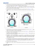
Page 13: ...ar rectangular instead of keystoned For more detailed instructions on positioning the projector refer to 2 2 1 Mounting later in this section STEP 3 Connecting a Source Located at the back of the projector is the input panel where all source connections are made Each input is clearly labeled for easy identification Depending on the type of option card installed connect your source using the approp...

Page 14: ...he projector Plug the 3 pronged plug end into a suitably rated grounded AC receptacle Do not attempt operation if the AC supply and cord is not within the specified ratings On power down wait 5 minutes for the fans to turn OFF before unplugging the projector STEP 5 Power up After the AC Power has been switched on the LCD display above the keypad indicates Please wait and the 4 LED status indicator...

Page 15: ...mation contact your dealer Use only the Christie approved ceiling mount kit designed for your projector Refer to the installation instructions and safety guidelines provided in the kit 2 2 2 Basic Optical Alignment Only perform image alignment once the projector is fully assembled and powered up in its final location Basic image alignment ensures the image reflected from the DMDs is parallel to an...

Page 16: ... parallel to the top edge of the screen 6 Throw Distance Ensure the projector is positioned in the throw distance range for the particular lens Folded Optics In rear screen applications where space behind the projector is limited a mirror may be used to fold the optical path see Figure 2 5 The position of the projector and mirror must be accurately set if considering this type of installation call...

Page 17: ...r pattern II by adjusting the appropriate cap screw see Figure 2 8 Adjust until the cross hair image is in focus with minimal flare 7 Adjust cross hair pattern III by adjusting the appropriate cap screw see Figure 2 8 Adjust until the cross hair image is in focus with minimal flare 8 Repeat step 5 6 and 7 as required until all 3 cross hair patterns are in equal sharp focus If the boresight is acce...

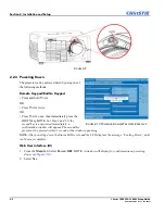
Page 18: ...press the DOWN key NOTE For Step 2 and 3 if the second key is not pressed immediately a confirmation window will appear The second key press must be pressed within 1 second of the window appearing NOTE After powering down the Status LEDs cycle and the LCD displays the message Cooling Down until cool down is complete Web User Interface UI 1 From the Main Tab Select Power OFF NOTE A window will disp...

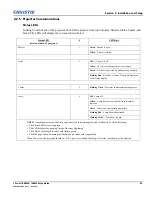
Page 19: ...Red Error has occurred Details are displayed on the status display Comm 3 Flashing Green Projector communication in progress Lamp 4 Off Lamp off Yellow Lamp time has expired and lamp should be replaced Green Lamp is on and operating normally Flashing Red Lamp has malfunctioned Flashing Yellow Lamp door is open NOTE A condition occurs on the first power on after a software upgrade and is indicated ...

Page 20: ......

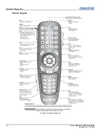
Page 21: ...the rear of the projector See Figure 3 2 While each of the keypads provides complete control of the projector they differ slightly in their arrangement of keys and in what functions can be accessed directly with a key press rather than requiring use of the menu system You may find one keypad more convenient than another for your specific installation and application Guide to Keypads Keep these gui...

Page 22: ...3 2 J Series 1000W 1200W Setup Guide 020 100740 02 Rev 1 03 2014 Section 3 Operation Remote Keypad FIGURE 3 1 REMOTE KEYPAD ...

Page 23: ...splay window which displays all states of the keypad controls The LCD displays status information when the projector is powering up Warm up Lamp is warming up and when the projector is cooling down Cool down Lamp is cooling down The display shows the state of the keys menu structure and menu items Overview of LED and Key States The LED color of the keys indicates that the key is in one of these st...

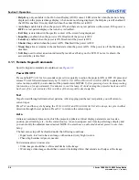
Page 24: ...jector ON or OFF Or press and release POWER followed immediately by UP ARROW KEY ON or DOWN ARROW KEY OFF to guarantee the correct action useful if you are unsure of the present state NOTES 1 After powering down the lamp cooling fan remains on for approximately five minutes to cool the lamp 2 Avoid turning the projector back on until it has been off for a few minutes Hot re strikes of the lamp wil...

Page 25: ...s later in this section Slot 1 2 3 4 Press to display the next active input on the card in the slot Input Displays all inputs in all slots both active and inactive Scroll through the list to select an input for the main image Press Input again to show the list and select the picture in picture PIP image PIP Turns PIP ON or OFF Swap Swaps the main and PIP images Contrast Changes the level of peak w...

Page 26: ...s HELP to display context sensitive help Press HELP again to toggle the help window OFF Menu Press MENU to enter or exit the menu system OSD On screen display Press OSD then the DOWN ARROW to hide the menu system during use To see the menus again do one of the following Press and hold OSD for two seconds Press and release OSD followed immediately by UP ARROW Press OSD OSD Invisible menus are fully...

Page 27: ... PROJ check box read only shows whether or not a projector connected to a keypad is receiving keypadf commands A checkmark indicates that the projector is receiving keypad commands To control a specific projector with the keypad press PROJ and then enter the three digit number assigned to the projector you want to use If you switch to a projector other than the one you are currently using the chec...

Page 28: ...nt the remote at the screen to highlight an area of your presentation NOTE Leave batteries in the wired remote keypad for the LASER key to work 3 2 Navigating the Menus Main Menu Most of the projector controls are accessed from within the projector menu system There are several groups of related functions with each group selectable from the Main menu as shown at right Press MENU at any time to dis...

Page 29: ...to change settings by using slide bars check boxes and pull down lists Navigating options Enter the menu option number corresponding to the setting you wish to change for example press MENU 1 3 to select Vertical Stretch in the Size and Position menu Move the highlight to the option desired and press ENTER Move the highlight to the option desired and press LEFT RIGHT ARROW KEY to adjust immediatel...

Page 30: ...eferences menu the slide bar just won t be visible 2 A direct slide bar disappears if it is not used within five seconds Check boxes Conditions are present if its adjacent check box contains a checkmark To toggle the check box highlight and press ENTER or highlight and use RIGHT ARROW KEY to check and LEFT ARROW KEY to uncheck If a check box is numbered enter its number to immediately toggle the c...

Page 31: ... the next available character of current text To convert a lower case letter into a capital letter position the cursor on the letter and press FUNC followed by the UP ARROW KEY To convert a capital letter into a lower case letter position the cursor on the letter and press FUNC followed by the DOWN ARROW KEY NOTE Also enter numbers directly from the keypad To convert a lower case capital letter po...

Page 32: ...value Press EXIT to cancel editing of numerical values 3 3 Alarms There are two types of alarms Warning Alarm Critical Alarm A warning alarm is generated when an error or a non optimal condition occurs that will not prevent the projector from operating An example is when a temperature is slightly elevated A critical alarm is generated when a condition occurs that could prevent the projector from o...

Page 33: ...limit risk of the lamp shattering increases as a result of changes in the quartz glass that occur with use Operation beyond the lamp warranty limit also significantly reduces brightness output Wait approximately 5 minutes after powering down the projector to allow the lamp to cool sufficiently before removing Never attempt to remove the lamp housing directly after use The lamp is under great press...

Page 34: ...n and unplug the projector prior to servicing Allow the lamps to cool before handling 3 REMOVE THE LAMP DOOR Protective gear required Wear a face shield Using a 2 Phillips screwdriver loosen the two 2 lock screws securing the lamp door which is located at the rear of the projector below the Input panel See Figure 4 1 FIGURE 4 1 Table 4 1 Projector Part Number Projector Model Lamp Type Lamp Filter ...

Page 35: ... MODULE Firmly grasp the lamp by its housing only and pull it straight out lamp slides along guides until it is free See Figure 4 3 Discard the lamp using safe disposal recycling practices FIGURE 4 3 6 RECORD THE SERIAL NUMBER OF THE NEW LAMP 7 INSERT THE NEW LAMP MODULE Align the new lamp with the top and bottom guides on the left side of the lamp compartment See Figure 4 4 Slide the lamp into th...

Page 36: ...ecommended for accurate lamp statistics to be archived Filter Replacement Procedure Only use Christie approved filters See Table 5 1 The filter located at the front side of the projector and should be replaced whenever the lamp is replaced If you are working in an extremely dusty environment you may want to replace the filter sooner If this filter is not replaced airflow may become restricted and ...

Page 37: ...Rotate the lens clamp to the OPEN position to remove old lens See Figure 4 6 FIGURE 4 6 2 Align the new lens interface plate with the lens mount Align the lens electrical connector with the mating connector on the lens mount Fully insert the assembly straight into the lens mount opening without turning Press using your hand as shown in Figure 4 7 NOTE Ensure the lens is not inserted at an angle as...

Page 38: ...the security screws provided with the lens mount See Figure 4 9 FIGURE 4 9 6 Use a 5mm hex driver to fasten the red security screws provided with the lens mount Figure 4 9 NOTES 1 Recommended for heaviest lenses such as 0 73 1 and 1 2 1 2 The red security screws MUST be installed when hoisting the projector overhead or installing the projector in an overhead position Use of the lens red security s...

Page 39: ...s tissue around a swab and soak it in coated optics cleaning solution Tissue should be damp but not dripping 3 Gently wipe the surface using a figure 8 motion Repeat this motion until the blemish is removed 4 4 Power Cord and Attachments Use only the AC power cord supplied Do not attempt operation if the AC supply and cord are not within the specified voltage and power range Refer to Section 6 Onl...

Page 40: ...teries 1 Open the battery compartment at the backside of the remote by placing your thumb finger in the oval depression and sliding the cover out about 1 2 inch Remote the old batteries and properly discard Wait a minute or two 2 Place the new batteries in the compartment orienting the positive negative of each battery according to the labels in the compartment 3 When the batteries are in place re...

Page 41: ...alizing the display should show Please wait When finished initializing the display should show Standby mode 4 Check the LCD display for any warnings or errors NOTE A condition occurs on the first power on after a software upgrade and is indicated by all the following The Status LEDs are cycling green The LCD displays the warning Image Processor Upgrading The LED on the Image Processor card flashes...

Page 42: ...if IR signals are received by the projector Pressing any key on the remote control towards the front or rear sensor the Status LED will blink regardless if any command is executed If the LED does not blink restart the projector 3 Ensure the remote keypad is enabled If the projector is powered using the built in keypad open the OSD menu and go to the Main Menu Configuration Communication submenu an...

Page 43: ...es should have the same subnet mask yet unique IP addresses 5 7 Displays 5 7 1 The projector is on but there is no display 1 Was a lens cover accidently left on Remove lens cover 2 On the LCD display check that the shutter is open This will also be indicated by the shutter LED being green 3 Is the correct input selected Check cable connections 4 Check if menus appear on the screen 5 Can you access...

Page 44: ...nly once 3 The source if non video may need a different sync tip clamp location 5 7 6 The Upper Portion of the Display is Waving Tearing or Jittering This can occur with video or VCR sources Check your source 5 7 7 Portions of the Display are Cut Off or Warped to the Opposite edge Resizing may need adjustment Adjust until entire image is visible and centered 5 7 8 Display Appears Compressed Vertic...

Page 45: ...t Rectangular 1 Check leveling of the projector Ensure the lens surface and screen are parallel to one another 2 Is the vertical offset correct Make the necessary adjustments to the vertical offset on the lens mount 5 7 14 Display is Noisy 1 Display adjustment at the input source may be required Adjust pixel tracking phase and filter Noise is particularly common on YPbPr signals from a DVD player ...

Page 46: ...aved After performing a backup of Interrogator you may be prompted from a pop up window before saving the file If you have not specifically set Internet Explorer to automatically open save the file without prompting and if pop up windows have been disabled by enabling the pop up blocker then you will not be able to save the file Disable the pop up blocker from Main Tools Pop up Blocker NOTE Differ...

Page 47: ...Section 5 Troubleshooting J Series 1000W 1200W Setup Guide 5 7 020 100740 02 Rev 1 03 2014 FIGURE 5 1 ...

Page 48: ......

Page 49: ...put Source Signal Compatibility 6 2 1 Analog Only Input 6 3 Control Signal Compatibility 6 3 1 Projector Control Filter media types Dust filter Fog filter Filter access Service interchangeable via access panel Cermax Xenon lamp system Lamps are accessed from the rear of the projector Analog Only Input Twin HDMI Input Dual Link DVI Input Video Decoder Input Dual SD HD SDI Input DMX512 Interface Rem...

Page 50: ...Cord 1000W 14AWG type SJT with plug NEMA 5 15P 15A 1200W 16AWG type SJT with plug NEMA 6 15P 13A Inrush Current All 60 A max Maximum Power Consumption 1000W 1200W 1200W 2000W Type Cermax Xenon Power 1000W 700W min 1000 W max software adjustable 1200W 800W min 1200W max software adjustable Rated lamp life to 50 brightness 2 hrs on 15 min off duty cycle 1000W 1 500 hours min 1200W 1 000 hours min Wa...

Page 51: ...HD 118 100115 XX X Lens ILS 7 5 11 2SX 6 9 10 4HD 118 100116 XX X Lens ILS 1 2SX 1 1HD 118 100117 XX X Lens ILS 1 2SX 1 1HD 118 101103 XX X ILS Lens Conversion Kit 108 331108 XX X Lens Conversion Kit 108 422109 XX X CT Mount Xe Cermax 132 111104 XX X Kit Upgrade to Mirage 132 101103 XX 132 102104 XX X YNF Upgrade 132 110103 XX X AutoSTACK 108 308101 XX X Handle 104 107101 XX X Edge Blending CT 104...

Page 52: ...ct must conform to EU Directive 2011 65 EU on the restriction of the use of certain hazardous substances RoHS in electrical and electronic equipment and the applicable official amendment s EU Regulation EC No 1907 2006 on the registration evaluation authorization and restriction of chemicals REACH and the applicable official amendments EU Directive 2012 19 EU on waste and electrical and electronic...

Page 53: ...de CCC KC PSE c tick CU South Africa Saudi Arabia and India International packaging recycling mark requirements EU Directive 94 62 EC on packaging and packaging waste China packaging recycling mark standard GB18455 2001 Korea extended producer responsibility EPR separate discharge mark system under the act on the promo tion of resource saving and recycling 2003 United States society of the plastic...

Page 54: ......

Page 55: ...nal I O devices to the projector There are 7 GPIO pins available on the 9pin D Sub GPIO connector which are configurable via RS 232 commands The other two pins are reserved for ground and power see table below for pin identification Table A 1 GPIO Pin The serial cable required for connecting the external device to the projector GPIO connector must be compatible with the external device GPIO PINS P...

Page 56: ... 3 3V A low state or value of 0 will be read on an input pin if the circuit attached to the pin is open A high state or value of 1 will be read on an input pin if the circuit attached to the pin is shorted to ground This corresponds to a switch closing event Example 1 Turn room lighting on when the projector is turned off Assumes a control automation unit is configured to turn the lights on when p...

Page 57: ......

Page 58: ...1 21 44 04 Germany ph 49 2161 664540 Eastern Europe and Russian Federation ph 36 0 1 47 48 100 United Arab Emirates ph 971 4 3206688 Spain ph 34 91 633 9990 Singapore ph 65 6877 8737 China Beijing ph 86 10 6561 0240 Republic of South Africa ph 27 0 11 510 0094 Corporate offices Worldwide offices India ph 91 080 6708 9999 Australia ph 61 0 7 3624 4888 Brazil ph 55 11 2548 4753 China Shanghai ph 86 ...

Reviews: