1.6.2 BATTERY CABINET CONNECTIONS
If the unit has been purchased with an optional extended runtime battery cabinet, connect
the battery cables to the UPS using the Black, Red and Green/Yellow cables provided in
flexible conduit. For units with internal batteries, skip to Section 1.6.3. On the UPS
module, attach the conduit to the knockout located beneath the battery terminals.
First,
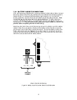
connect the green and yellow wire to the ground terminal
. The Black cable then
connects to the Battery Negative (-) and Red Cable connects to the Battery Positive (+)
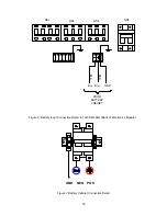
See Figures G or H.
Ensure that the battery disconnect switch (QS5) is in the OFF (0)
position before completing the interconnect wiring.
Attach the other end of the conduit to the knockout hole in the bottom, rear of the battery
cabinet. (Note: the cover panel on the back of the battery cabinet must be removed to
gain access to the conduit holes and terminal blocks.) Connect the battery cables to the
battery cabinet terminals (see
Figure
I
).
Once these wires are connected, connect the
quick-connect terminals protruding through the frame of the cabinet per the interconnect
instruction sheet provided with the battery cabinet.
R
E
D
B
LK
G
R
N
/Y
E
L
B(-) B(+) GND
TO
BATTERY
CABINET
(Back of Electronics Module)
Figure G:
Battery Input Connection Detail: 4-6kVA Modules
17


