


36
AS400 CARD
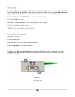
The AS400 (Relay) card is equipped with a “D”-type female 9-pin connector comprising voltage-free contacts and conforming to
the requirements of IBM AS/400 and other computing systems.
Figure - 14
AS400 ( Relay) card.
The interface communication pin layout is as follows
•
Pin 1 is Bypass
•
Pin 2 is Summary Alarm
•
Pin 3 is Shutdown (+)
•
Pin 4 is Shutdown (-)
•
Pin 5 is the common for all contact on internal relays.
•
Pin 6
is Low Battery (N/C)
•
Pin 7 is Low Battery (N/O)
•
Pin 8 is AC Fail (N/C)
•
Pin 9 is AC Fail (N/O)
Summary of Contents for CP3000 Series
Page 22: ...13 UPS Top Plate template ...
Page 23: ...14 UPS Bottom Plate template ...
Page 27: ...18 Figure 9 GCAB ...
Page 28: ...19 Battery Cabinet Conduit Plate Template ...
Page 32: ...23 Menu Structure ...


