www.chipsee.com
www.chipsee.com
Expansion Connector
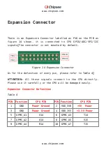
There is an Expansion Connector labelled as P18 on the PCB as
figure 14 shown, it is connected to CPU GPIO/ADC/SPI/I2C
signals。The connector is not mounted by default.
Figure 14 Expansion Connector
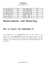
As for the definition of every pin, please refer to Table 4。
ATTENTION: All these signals connect to the CPU directly.
Please use it carefully or the CPU will be damaged easily.
Expansion Connector Definition
Table 4
PIN Function
CPU PIN
PIN Function
CPU PIN
1
GND
Power Ground
2
VDD_5V0
+5V Power
3
GND
Power Ground
4
VDD_3V3
+3.3V Power
5
GPMC_A1
V14
6
GPMC_A3
T14
7
GPMC_A2
U14
8
GPMC_A5
V15
9
GPMC_A4
R14
10
GPMC_A7
T15
Summary of Contents for CS10600T070E-C211
Page 1: ...www chipsee com www chipsee com PPC EPC A8 70 HB C User Manual Release 1 0...
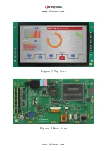
Page 6: ...www chipsee com www chipsee com Figure 1 Top View Figure 2 Back View...
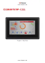
Page 7: ...www chipsee com www chipsee com CS10600T070P C211 Figure 1 Top View...

