Copyright CPS America Co., Ltd. Page 29
E. Communications slot for Modbus
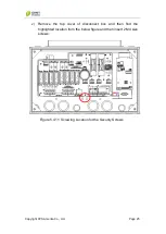
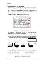
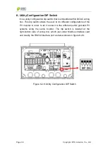
PV inverter has an extended slot for a communication interface in the
wiring box as indicated in the figure below. Through installing a Modbus
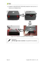
card to use this slot, please remove the cover of the wiring box following
(Please refer to page 24) insert the card into the slot reinstalled the cover
of the wiring box (Please refer to page 52).
For further information, please contact with your dealer.
Figure 6.2.2: Connection slot for Modbus
After installation of Modbus card, user can link PC with Inverters and
monitor their real-time operation status remotely.
When wiring Modbus card from Inverter to Modbus/ RS485 to RS232
Converter, we connect opposite pins of Modbus which means Receive Pin
to Transmit Pin, and Transmit Pin to Receive Pin. See framed area below.
Figure 6.2.3: Framed area of Connection
Inverter
DC In AC Out
Converter
Inverter
DC In AC Out
Inverter
Modbus/RS485
DC In AC Out
Remote Computer
RS232
or other
media
Inverter to inverter correct pin configuration:
Pin T+(T) to T+(T)
Pin T-(Transmit-) to T-(Transmit-)
Pin R+() to R+()
Pin R-(Receive-) to R+(Receive-)
Inverter to logger correct pin configuration:
Pin T+(T) to R+()
Pin T-(Transmit-) to R-(Receive-)
Pin R+() to T+(T)
Pin R-(Receive-) to T-(Transmit-)
Modbus/RS485
Modbus/RS485
Modbus/RS485

