background image

Vari Pro FCU Controller Card Register Map v 1.4

Modbus RTU RS485 38400, 8N1

Description

Read/
Write

Min.

Max.

Unit

Note(s)

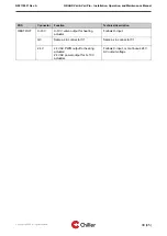
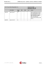
3x00013

Heating output

R

0

1000

xx10mV

Scaled to maximum flow

3x00018

Temperature
water in

R

x10C

3x00019

Temperature
water out

R

x10C

3x00025

Service
reminder
counter

R

h

(*) Reading via User Interface

Address: 3x00N (RR-2)

N = Unit count

RR = Register address

Example: 3x00010 (Condensate tank state) from 1st unit, user interface address 3x00108

Copyright © 2020. All rights reserved.

41 (45)

N02119031 Rev. A

GRAND Vari & Vari Pro – Installation, Operation, and Maintenance Manual

Summary of Contents for BOX Vari

Page 1: ...EN Installation Operation and Maintenance Manual GRAND Vari Vari Pro N02119031 Rev A ...
Page 2: ...ller Oy is constantly developing its products and reserves the right to change its products GRAND Vari is a registered trademark of Chiller Oy All rights reserved Chiller Oy 2020 Chiller Oy Address Louhostie 2 FI 04300 Tuusula Finland Telephone 358 9 274 7670 E mail info chiller fi Internet www chiller eu Approvals and version history REVISION DATE DESCRIPTION OF CHANGE APPROVED BY A 25 05 2020 Fi...

Page 3: ...e without condensation water pump 21 4 6 2 Sewerage with condensation water pump option 22 4 7 Attaching the electrical connections 25 4 8 Installing the external drain pan 26 4 9 Installing the fresh air connection 27 4 10 Installing the grille 27 4 11 Testing the condensation water pump 28 5 Operation of the unit 30 5 1 Controlling the unit 30 6 Maintenance of the unit 31 6 1 Maintenance schedul...

Page 4: ...omes void if the product is modified or repaired without a written consent from Chiller Oy the unit parameters are modified without permission the configuration of the unit is changed the installation site unit connections installation ground or installation procedures do not follow these instructions the instructions in this Installation Operation and Maintenance Manual are not followed The guara...
Page 5: ...eller of them b Record the transport damages on the bill of freight c Send a complaint about the damages to the transport company within 24 hours of delivery 1 4 Related documentation In addition to this manual the unit is delivered with a unit specific wiring diagram In case you need a new wiring diagram you can order it You need the unit serial number from the type plate for the order see Sectio...

Page 6: ... WARNING WARNING indicates a hazard with a medium level of risk which if not avoided could result in death or serious injury CAUTION CAUTION indicates a hazard with a low level of risk which if not avoided could result in minor or moderate injury Note Notes are used to indicate important information and useful tips 2 3 Safety symbols Hazard symbols These symbols indicate a hazardous situation or a...

Page 7: ... below Limited or restricted access Do not touch Mandatory action symbols These symbols are used in warnings and notifications to indicate an action that must be taken The mandatory action symbols are shown below Read the manual or instructions Copyright 2020 All rights reserved 7 45 N02119031 Rev A GRAND Vari Vari Pro Installation Operation and Maintenance Manual ...

Page 8: ...nections 3 External drain pan 4 Free drain outlet option if the unit is without condensate pump 5 Condensate pump outlet option 6 Electrical box 7 Fresh air connection Ø 125 mm 8 Collar 9 Maintenance hatch 10 Grille The unit directs air to the room from the upper side of the grille blue arrow and returns the air back to the unit from the bottom side red arrow There is a separator plate inside the ...

Page 9: ...n 4 4 Mounting the unit 3 2 Unit dimensions The unit comes in two sizes Grand 70 and Grand 100 Note The unit dimensions are given as reference Chiller Oy reserves the right to make changes to them Check the actual dimensions from the order documentation Figure 3 Main dimensions of Grand 70 Copyright 2020 All rights reserved 9 45 N02119031 Rev A GRAND Vari Vari Pro Installation Operation and Mainte...

Page 10: ...nd filter Note Record the type plate information on the unit card and file it carefully The type and serial numbers of the unit are required for identifying the unit when for instance purchasing spare parts When you order maintenance or order spare parts you always need the serial number You cannot make an order without the serial number Copyright 2020 All rights reserved 10 45 N02119031 Rev A GRA...

Page 11: ...on options and control connections The unit is available with two automation options referred to as Vari and Vari Pro The automation option is selected during the unit order Once the unit is delivered you can see the automation type on the type plate Type unit type is either Vari or Vari Pro The automation option of the unit affects the way the fan coil is controlled and what external equipment ca...

Page 12: ...room controller Potential free alarm contact open in alarm or when unit not powered No additional sensor inputs or control outputs See Appendix A Vari option control connections for further details Figure 6 Vari control card Figure 7 Vari wiring instructions on the electrical box cover Copyright 2020 All rights reserved 12 45 N02119031 Rev A GRAND Vari Vari Pro Installation Operation and Maintenan...

Page 13: ...unit order process No analogue control options Note Vari Pro has advanced timed functions such as valve exercise every 24 hours The unit will resume normal operation after the timed function has ended See Appendix B Register listing for Vari Pro option for further details Figure 8 Vari Pro control card Figure 9 Vari Pro wiring instructions on the electrical box cover Copyright 2020 All rights rese...

Page 14: ...or for using the unit in conditions that differ from those specified in Section 4 2 Choosing the installation site The installation concept Install Use Maintain is applied with this unit The installation order of this concept is installation on the ceiling pipe connections electrical connections external drain pan grille testing and commissioning of the unit Note Do not remove any of the coverings...

Page 15: ... so that it allows free air circulation in the unit the unit must not be installed in a room where recirculation air can bring such substances to the inlet opening of the unit that block air circulation for instance greases from the kitchen the installation and maintenance room required for electrical installations pipe laying and installation of sewerage for condensation water Table 1 Limitations...

Page 16: ...stallation openings A B C D E Grand Vari 70 665 5 mm 180 5 mm 720 mm 600 mm 433 483 mm Grand Vari 100 990 5 mm 180 5 mm 1020 mm 600 mm 433 483 mm 4 3 Removing the air duct collar If the unit is delivered with the air duct installed the air duct collar must be removed before mounting the unit to the ceiling Copyright 2020 All rights reserved 16 45 N02119031 Rev A GRAND Vari Vari Pro Installation Op...

Page 17: ...g points The mounting points are integrated in the unit frame DANGER Risk of severe injury Make sure you attach the unit firmly to the ceiling If the unit is not properly attached it can fall and cause severe injury Copyright 2020 All rights reserved 17 45 N02119031 Rev A GRAND Vari Vari Pro Installation Operation and Maintenance Manual ...

Page 18: ...u can hoist the unit on the ceiling by using a drywall panel lift or similar WARNING Use a hoist that is rated to handle the weight of the unit a If you use threaded bars for supporting the unit you must secure the joint between the threaded bar and the support with locknuts and washers b Make sure that the bars are attached tightly to the ceiling and they do not come off 3 Make sure that the dist...

Page 19: ...Make also sure that the separator plate is horizontally levelled CAUTION The separator plate must be horizontally leveled If the plate is not leveled the air does not circulate properly in the unit and the unit does not function as intended 6 Install the accessories control valves shut off valves external drain pan etc if they are delivered as separate items Copyright 2020 All rights reserved 19 4...

Page 20: ...u connect the unit to a cooling and or heating water circulation make sure that the water in the water circuit has a a maximum operation pressure of 10 bar b a minimum temperature of 4 C inlet water Note Water must never be allowed to freeze inside the coil condensate basin or piping of the unit c a maximum temperature of 80 C inlet water 2 Attach the water connections as shown below 1 Heating wat...

Page 21: ...il or internal pipework 4 6 Installing sewerage for condensation water The factory made Grand unit is available without or with optional condensation water pump Note Always follow the national construction regulations when you install the sewerage For further information on installing the sewerage for condensation water see Sections 4 6 1 Sewerage without condensation water pump and 4 6 2 Sewerage...

Page 22: ...w 4 6 2 Sewerage with condensation water pump option The Grand unit is available with a condensation water pump for a rise of 500 mm The pump pressure side has an outlet pipe plastic outer diameter 15 mm inner diameter 12 mm that is connected to a fixed condensation water pipework The outlet set for condensation water is located on the same side as the water sets in the unit Copyright 2020 All rig...

Page 23: ...ion water is directed to the sewerage system of the property The drain trap is dimensioned according to the installation height to ensure that water is constantly discharged at a sufficient rate the condensation water pipe is insulated if the unit is installed in rooms where condensation can occur on the pipe surface you support the condensation water pipe so that it does not bend at any place you...

Page 24: ...he piping so that the pressure variations caused by the condensation water pump do not remove the hose from the pipe If necessary use a seal Note Do not push the hose too far into the sewerage pipe The hose s end should be about 30 50 mm inside the seal you cut the hose to a suitable length Copyright 2020 All rights reserved 24 45 N02119031 Rev A GRAND Vari Vari Pro Installation Operation and Main...

Page 25: ...sure that the condensation pump hose does not block the sewerage 4 After installation make sure that the horizontal inclination of the fall for the condensation sewerage is at least 2 4 7 Attaching the electrical connections DANGER Electrocution hazard Touching live parts or components of the unit can cause severe injury or death Only qualified persons are allowed to perform electrical work on the...

Page 26: ...re that the supply of the unit is protected by means of a front fuse 2 If several units are connected in parallel behind the same supply make sure that the size and sufficiency of the fuse is sufficient for unit specific protection 3 Make sure that the cable is dimensioned in accordance with the maximum values that are specified in the type plate of the unit See Section 3 3 Type plate Note The pow...

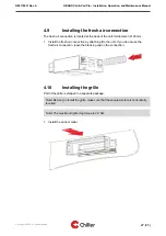
Page 27: ...nnection leave the blanking cap on the connection 4 10 Installing the grille Part of the grille is shipped in a separate package Note Before you install the grille make sure that the separator plate is horizontally levelled Note The maximum tightening torque is 2 2 Nm 1 Install the air duct collar Copyright 2020 All rights reserved 27 45 N02119031 Rev A GRAND Vari Vari Pro Installation Operation a...

Page 28: ...the unit Do not operate the unit before you have run the test successfully Before you can operate the unit you must test the condensation water pump Run a leak test after you have mounted the unit on the ceiling and done the necessary electrical and pipe connections Copyright 2020 All rights reserved 28 45 N02119031 Rev A GRAND Vari Vari Pro Installation Operation and Maintenance Manual ...

Page 29: ... stops after the water has gone to the sewerage d there are no leaks anywhere in the system Note The leak test has been successful if the pump starts moves the water stops and there are no leaks 3 If the leak test was successful you can start to use the unit 4 If the leak test failed do not use the unit before you have run another successful test Copyright 2020 All rights reserved 29 45 N02119031 ...

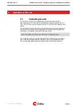
Page 30: ...of the unit to achieve the set room temperature The control valve and speed are controlled by a separate room house automation control Note This applies only if the unit contains two or three way valves The condensate pump is controlled internally The condensate pump operates even if the unit is stopped with the controller or the house automation control The unit operates independently according t...

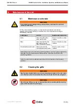
Page 31: ...n Drain and clean the condensation water basin Every 5 years or when needed Note If there are local and or site specific regulations such as hygiene regulations that differ from the maintenance schedule above follow the local and or site specific regulations Note You can find more detailed instructions for maintenance in the following sections 6 2 Cleaning the grille WARNING Electrocution hazard B...

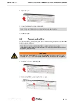
Page 32: ...filters regularly at least once a year depending on the conditions of the installation site Regular maintenance ensures a longer life cycle for the unit WARNING Electrocution hazard Before you do any maintenance work on the unit make sure that the unit is disconnected from the circuit and that it is de energized 1 To remove the filter open the grille 2 Remove the filters by opening the filter latc...

Page 33: ... Replace the filter if you cannot clean the filter as required or if the filter is damaged WARNING Electrocution hazard Before you do any maintenance work on the unit make sure that the unit is disconnected from the circuit and that it is de energized 1 To clean the filter lift the grille open 2 Remove the filters 3 Clean the filter from dust by vacuuming it Copyright 2020 All rights reserved 33 4...

Page 34: ...is dry 6 Attach the filters 7 Close the grille 6 5 Opening the maintenance hatch 1 Open the maintenance hatch WARNING Always support the maintenance hatch with one hand while opening The hatch will fall off and can cause injury if it is not supported Copyright 2020 All rights reserved 34 45 N02119031 Rev A GRAND Vari Vari Pro Installation Operation and Maintenance Manual ...

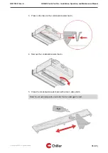
Page 35: ...cuit and that it is de energized Note You can access the unit for maintenance from the lower surface of the unit 1 Open and remove the maintenance hatch See Section 6 5 Opening the maintenance hatch for further instructions 2 Disconnect the pipe from the condensation water basin Copyright 2020 All rights reserved 35 45 N02119031 Rev A GRAND Vari Vari Pro Installation Operation and Maintenance Manu...

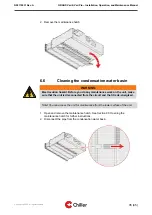
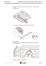
Page 36: ...ndensation water basin 5 Clean the condensation water basin with a clean damp cloth Note Do not use detergents or solvents that can damage the unit Copyright 2020 All rights reserved 36 45 N02119031 Rev A GRAND Vari Vari Pro Installation Operation and Maintenance Manual ...

Page 37: ...at the basin is properly attached and in its place 9 Attach the pipe 10 Pour water to the basin Test that the condensation water pump sewerage works correctly 11 Attach and close the maintenance hatch Copyright 2020 All rights reserved 37 45 N02119031 Rev A GRAND Vari Vari Pro Installation Operation and Maintenance Manual ...

Page 38: ...ode detected automatically C Cooling valve control input 0 10 V linear or 24 V AC DC for ON OFF control Impedance 50 kΩ Desired control mode detected automatically H Heating valve control input 0 10 V linear or 24 V AC DC for ON OFF control Impedance 50 kΩ Desired control mode detected automatically C3 1 Fixed fan speed 1 control input 24 V AC or DC control When active takes priority over F contro...

Page 39: ...ut G0 Same as in connector C1 Same as in connector C1 24 V 24 V AC PWM output for heating actuator 24 V AC power output for 0 10 V actuators Follows C input or continuous 24 V AC output voltage Copyright 2020 All rights reserved 39 45 N02119031 Rev A GRAND Vari Vari Pro Installation Operation and Maintenance Manual ...

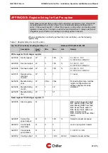
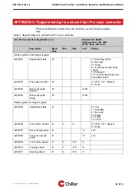
Page 40: ... 4x00003 Set cool output W 0 100 0 100 0 10 V 0 OFF 100 ON 24 V 4x00004 Set heat output W 0 100 0 100 0 10 V 0 OFF 100 ON 24 V 4x00101 Reset service reminder counter W 0 1 1 reset 4x35203 Manufacturing year W 20xx 20xx By reading this data modbus register configuration and address alignment can be validated 4x35204 Manufacturing month W 1 12 4x35205 Manufacturing day W 1 31 Read register 16 bit in...

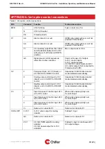
Page 41: ...8 Temperature water in R x10C 3x00019 Temperature water out R x10C 3x00025 Service reminder counter R h Reading via User Interface Address 3x00N RR 2 N Unit count RR Register address Example 3x00010 Condensate tank state from 1st unit user interface address 3x00108 Copyright 2020 All rights reserved 41 45 N02119031 Rev A GRAND Vari Vari Pro Installation Operation and Maintenance Manual ...

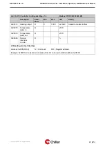
Page 42: ... 4 Flush set cool heat 100 5 Stopped 10 Test mode allow cool heat without fan 4x00003 Fan speed control W 0 OFF 1 3 Speed 4 Auto 4x00004 Room set point Normal W x10C 4x00005 Room set point Away W x10C Read register 16 integer register 3x00004 Application state R 0 Init 1 StandBy 2 Normal 3 Away 4 Flush 10 Test 3x00006 Current fan control R 0 4 0 OFF 1 3 Speed 4 Auto 3x00007 Room temperature R C x1...

Page 43: ...3 Alarm Unit 1 R Bit0 Condense sensor alarm Bit1 Missing RPM from fan1 Bit2 Missing RPM from fan2 Bit3 Sensor fault water in Bit4 Sensor fault water out Bit11 Parameter file Bit15 Service reminder Filter alarm 3x00203 Alarm Unit 2 R Copyright 2020 All rights reserved 43 45 N02119031 Rev A GRAND Vari Vari Pro Installation Operation and Maintenance Manual ...

Page 44: ......

Page 45: ...iller fi Chiller Lahti Rajavartijankatu 9 15170 Lahti Tel 358 3 876 470 lahti chiller fi Chiller Tampere Aunankorvenkatu 9 33840 Tampere Tel 358 3 214 3250 tampere chiller fi Chiller Turku Ahokylänkatu 3 20780 Kaarina Tel 358 10 229 0850 turku chiller fi Estonia Estonia Chiller Oy Tel 372 506 2986 ain kuus chiller fi Sweden Chiller Sverige AB Ekerö Tel 46 85 450 2080 info chillersverige se www chi...

Reviews: