background image

 MSA/MTA Series

Installation Instructions

8

11. Use two 5/16 x 2-1/2" lag bolts (QC) and two 5/16" flat 

washers (QB) to attach the mount to the wall through the 

lower mounting holes. (See Figure 4)

12. Slide rails to approximate center of screen location.

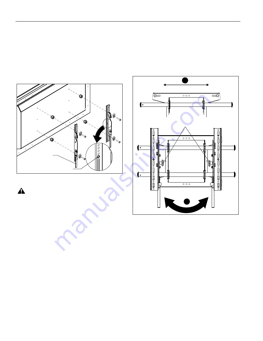
Attaching Interface Brackets to TV

1.

Align the center of the bracket with center of screen.         

(See Figure 4)

NOTE:  

The diamond-shape hole in the bracket corresponds to  

the center of the mount.

Figure 5 

WARNING:  

IMPROPER INSTALLATION CAN LEAD TO 

DISPLAY FALLING CAUSING SERIOUS PERSONAL 
INJURY OR DAMAGE TO EQUIPMENT! Using screws of 
improper size may damage your display. Properly sized 
screws will easily and completely thread into display 
mounting holes. If spacers are required, be sure to use longer 
screws of the same diameter.

2.

Select correct screws, spacers (if necessary) and washers 

from the hardware bag (A-N) and attach brackets to back of 

screen. (See Figure 5)

Switching Interface Brackets (Optional)

If an installation situation makes adjusting the location of 
interface brackets necessary, there are several options.
1.

The wall bracket may be adjusted side to side at the points 

of attachment. (See Figure 6)

2.

The location of the left and right interface brackets may be 

switched, with the knobs on the MTA interface brackets 

facing the inside of the mount. (See Figure 6)

Figure 6

3.

If necessary, the tilt interface bracket knobs may be 

switched to allow the interface brackets to be reversed. 

(See Figure 7)

a.  Remove display from mount.
b.  Remove interface brackets from display.
c.  Hold the right interface bracket horizontally, tightly 

gripping it so that spacers do not move. 

d.  Remove the knob, washer and screw.
e.  Replace the knob, washer and screw in the opposite 

order, with the knob on the inside of the bracket.

f.  Switch the right interface bracket to the left side of the 

wall mount. 

g.  Repeat Steps 3c through 3f with the left interface 

bracket.

Center of bracket

Pull strap

1

2

Knobs

Summary of Contents for Wall Mount PDWP MB 40 L

Page 1: ... I N S T R U C T I O N S И Н С Т Р У К Ц И И П О У С Т А Н О В К Е Instrucciones de instalación Installationsanleitung Istruzioni di installazione Installatie instructies MSA MTA FUSION MEDIUM FLAT PANEL MOUNTS MSA MTA Series ...

Page 2: ...he possibility of damage or destruction of equipment if you do not follow the corresponding instructions WARNING Failure to read thoroughly understand and follow all instructions can result in serious personal injury damage to equipment or voiding of factory warranty It is the installer s responsibility to make sure all components are properly assembled and installed using the instructions provide...

Page 3: ... CAN BE SLID LEFT OR RIGHT FOR OFFSET APPLICATIONS 4 MOUNT IS 1 99 50 5mm DEEP WHEN FLAT TO WALL MTA DIMENSIONS MILLIMETERS INCHES 25 57 649 5 18 75 476 2 75 19 1 1 50 38 1 1 50 38 1 34 8 6 9 58 243 4 11 00 279 4 13 50 342 9 16 00 406 4 8 00 203 2 1 96 49 8 13 50 342 9 16 78 426 1 32 8 1 38 9 6 65 16 5 98 25 0 49 12 5 1 97 50 2 46 62 5 3 94 100 4 43 112 5 5 91 150 6 40 162 5 7 87 200 49 12 5 1 97 ...

Page 4: ...el Chave de bocas Chiave a punte aperte Steeksleutel Clé à fourche By Hand A mano Von Hand Com a mão A mano Met de hand À la main Hex Head Wrench Llave de cabeza hexagonal Sechskantschlüssel Chave de cabeça sextavada Chiave esagonale Zeskantsleutel Clé à tête hexagonale Pencil Mark Marcar con lápiz Stiftmarkierung Marcar com lápis Segno a matita Potloodmerkteken Marquage au crayon Drill Hole Perfo...

Page 5: ...rdware Included with MSA6XXX MTA6XXX Models Only C 6 E 6 MSA Only MTA Only T 1 S 1 MSA Only MTA Only A 8 M4x16mm B 6 M4x20mm M4x25mm D 6 M5x16mm M5x20mm F 6 M5x25mm G 6 M6x16mm H 6 M6x25mm P 1 M5 I 6 M8x20mm J 6 M8x30mm K 4 M8x50mm L 8 750x 323x 250 M 8 750x 344x 500 N 8 QA 4 5 16 QB 4 5 16 QC 4 5 16 x 2 1 2 A N used on MSAU MTAU Models Only R 1 U 1 V 1 W 1 X 1 ...

Page 6: ... if using the single stud installation method NOTE Use that stud and the stud to either the left or right of it if using the dual stud installation method 3 Line up the notches on mount with center of screen marking to determine vertical center See Figure 1 4 Measure up 6 152 4mm from the center point to mark location of the upper mounting slots Figure 1 5 Using a level mark the wall on each stud ...

Page 7: ... to mark location of the upper mounting slots See Figure 1 4 Using a level mark the wall through both upper mounting slots See Figure 4 WARNING ELECTRICAL SHOCK HAZARD CUTTING OR DRILLING INTO ELECTRICAL CORDS OR CABLES CAN CAUSE DEATH OR SERIOUS PERSONAL INJURY ALWAYS make certain area behind mounting surface is free of electrical wires and cables before drilling or installing fasteners WARNING E...

Page 8: ...tach brackets to back of screen See Figure 5 Switching Interface Brackets Optional If an installation situation makes adjusting the location of interface brackets necessary there are several options 1 The wall bracket may be adjusted side to side at the points of attachment See Figure 6 2 The location of the left and right interface brackets may be switched with the knobs on the MTA interface brac...

Page 9: ...igure 8 Figure 8 2 Hang top hook of interface brackets onto the top bar of the mount See Figure 9 NOTE The screen initially installs into the kickstand mode to allow easy cable access 3 Slide screen and bars to desired viewing position 4 Route cables between wall and bars CAUTION PINCH POINTS Keep fingers hands and cables out of pinch point areas 3d 3e Knobs to outside of brackets Both interface b...

Page 10: ...wer bar and locking bottom of screen to the mount See Figure 9 Figure 9 Locking Mount Optional 1 Add optional security bracket S or T to the mount See Figure 10 2 Add padlock not included to complete security Figure 10 Screen not shown for clarity 2 5 Top Hook Pullstraps S 1 2 MTA Shown Padlock shackle diameter Min 1 4 6 3mm Max 5 16 7 9mm ...

Page 11: ...Installation Instructions MSA MTA Series 11 ...

Page 12: ... P 31 0 495 580 852 F 31 0 495 580 845 Asia Pacific A Office No 1 on 12 F Shatin Galleria 18 24 Shan Mei Street Fotan Shatin Hong Kong P 852 2145 4099 F 852 2145 4477 MSA MTA Series Installation Instructions Chief Manufacturing a products division of Milestone AV Technologies 8831 000025 Rev04 2012 Milestone AV Technologies a Duchossois Group Company www chiefmfg com 06 12 ...

Page 13: ...alao Istruzioni di installazione Installatie instructies Instructions dinstallation MSA MTA FUSION СРЕДНИЕ КРОНШТЕЙНЫ ДЛЯ ПЛОСКИХ ЭКРАНОВ Описание изделия на испанском Описание изделия на немецком Описание изделия на португальском Описание изделия на итальянском Описание изделия на нидерландском Серия MSA MTA ...

Page 14: ...троя оборудования при невыполнении соответствующих инструкций ПРЕДУПРЕЖДЕНИЕ Невнимательное прочтение и несоблюдение следующих инструкций может привести к получению серьезных травм повреждению оборудования или прекращению действия заводской гарантии Обязанность лица выполняющего установку с помощью предоставленных инструкций убедиться что все компоненты правильно собраны и установлены ПРЕДУПРЕЖДЕН...

Page 15: ...О СДВИНУТЬ ВЛЕВО ИЛИ ВПРАВО ДЛЯ СДВИГАЕМЫХ КРЕПЛЕНИЙ 5 КРОНШТЕЙН ГЛУБИНОЙ 50 5мм 1 99 ДЛЯ ПЛОСКОГО КРЕПЛЕНИЯ К СТЕНЕ ПРИМЕЧАНИЯ 25 57 649 5 18 75 476 2 75 19 1 1 50 38 1 1 50 38 1 34 8 6 9 58 243 4 11 00 279 4 13 50 342 9 16 00 406 4 8 00 203 2 1 96 49 8 13 50 342 9 16 78 426 1 32 8 1 38 9 6 65 16 5 98 25 0 49 12 5 1 97 50 2 46 62 5 3 94 100 4 43 112 5 5 91 150 6 40 162 5 7 87 200 49 12 5 1 97 50 ...

Page 16: ...ЫЕ ОБОЗНАЧЕНИЯ Затянуть крепежный элемент Ослабить крепежный элемент Крестообразная отвертка Открытый рожковый ключ Вручную Ключ с шестигранной головкой Карандашная пометка Просверлить отверстие Отрегулировать Удалить Дополнительно Специальный ключ ...

Page 17: ...олько с моделями MSA6XXX MTA6XXX C 6 E 6 Только для MSA Только для MTA S 1 Только для MSA Только для MTA T 1 A 8 M4x16 мм B 6 M4x20 мм M4x25 мм D 6 M5x16 мм M5x20 мм F 6 M5x25 мм G 6 M6x16 мм H 6 M6x25 мм P 1 M5 I 6 M8x20 мм J 6 M8x30 мм K 4 M8x50 мм L 8 750x 323x 250 M 8 750x 344x 500 N 8 QA 4 5 16 QB 4 5 16 QC 4 5 16 x 2 1 2 R 1 A N используется только на моделях MSAU MTAU U 1 V 1 X 1 W 1 ...

Page 18: ...ее при монтаже на одну стойку ПРИМЕЧАНИЕ Используйте эту стойку и стойку слева или справа от нее при монтаже на две стойки 3 Совместите прорези на креплении с отметкой середины экрана чтобы определить середину по вертикали См рис 1 4 Отмерьте 152 4 мм вверх от средней линии и отметьте место верхнего монтажного отверстия рис 1 5 При помощи уровня сделайте на стене отметки на каждой из стоек каркаса...

Page 19: ...инии и отметьте место верхнего монтажного отверстия См рис 1 4 При помощи уровня сделайте на стене отметки в местах размещения верхних монтажных отверстий См рис 4 ПРЕДУПРЕЖДЕНИЕ ОПАСНОСТЬ ПОРАЖЕНИЯ ЭЛЕКТРИЧЕСКИМ ТОКОМ РАЗРЕЗАНИЕ ИЛИ ПРОСВЕРЛИВАНИЕ ПРОВОДА ИЛИ КАБЕЛЯ МОЖЕТ ПРИВЕСТИ К СЕРЬЕЗНЫМ ТРАВМАМ В ТОМ ЧИСЛЕ СО СМЕРТЕЛЬНЫМ ИСХОДОМ Перед сверлением отверстий или установкой крепежных элементов ...

Page 20: ... и прикрепите соединительные кронштейны к тыльной стороне экрана См рис 5 Перестановка соединительных кронштейнов дополнительная возможность Если в ходе установки возникает необходимость изменить положение соединительных кронштейнов это можно сделать несколькими способами 1 Кронштейн можно сдвинуть горизонтально в ту или другую сторону относительно точки крепления См рис 6 2 Левый и правый соедини...

Page 21: ...штейнов на верхнюю рейку системы крепления См рис 9 ПРИМЕЧАНИЕ Первоначально экран устанавливается на некотором расстоянии от стены как при использовании выдвижной опоры чтобы облегчить доступ к кабелю 3 Установите экран и рейки в положение нужное для просмотра изображения 4 Проложите кабели между стеной и рейками ВНИМАНИЕ ЗОНЫ ЗАЩЕМЛЕНИЯ Следите за тем чтобы пальцы руки и кабели не попадали в зон...

Page 22: ...й экрана в системе крепления См рис 9 рис 9 Запирание крепления необязательно 1 Установка на крепление дополнительной защитной скобы S или T См рис 10 2 Установка висячего замка не входит в комплект для полной безопасности рис 10 Экран не показан для большей наглядности 2 5 Крепежные ленты Верхняя скоба S 1 2 Показана модель MTA Диаметр скобы висячего замка Мин 6 3 мм 1 4 Макс 7 9 мм 5 16 ...

Page 23: ...Инструкции по установке Серия MSA MTA 23 ...

Page 24: ...fmfg com 06 12 США Международное представительство Адрес 6436 City West Parkway Eden Prairie MN 55344 тел 800 582 6480 952 225 6000 факс 877 894 6918 952 894 6918 Европа Адрес Franklinstraat 14 6003 DK Weert Netherlands тел 31 0 495 580 852 факс 31 0 495 580 845 Азия и Тихоокеанский регион Адрес Office No 1 on 12 F Shatin Galleria 18 24 Shan Mei Street Fotan Shatin Hong Kong тел 852 2145 4099 факс...

Reviews: