


Chief Manufacturing, a division of Milestone AV Technologies
1-800-582-6480
952-894-6280 Fax: 952-894-6918
8401 Eagle Creek Parkway
Savage, Minnesota 55378 USA
8832-000166
2008 Milestone AV Technologies
www.chiefmfg.com
06/08
I N S T A L L A T I O N I N S T R U C T I O N S
BEFORE YOU BEGIN
Small Flat Panel Desk Mounts
Models: MSP-TDKCG110 &
MSP-TDKCY220
Specifications:
•
Designed for edge or grommet (hole) installation.
•
Accommodates VESA compliant 75mm x 75mm,
or 100mm x 100mm display mounting pattern.
IMPORTANT ! :
See "IMPORTANT WARNINGS AND
CAUTIONS" on page 2 for weight capacities of these
mounts.
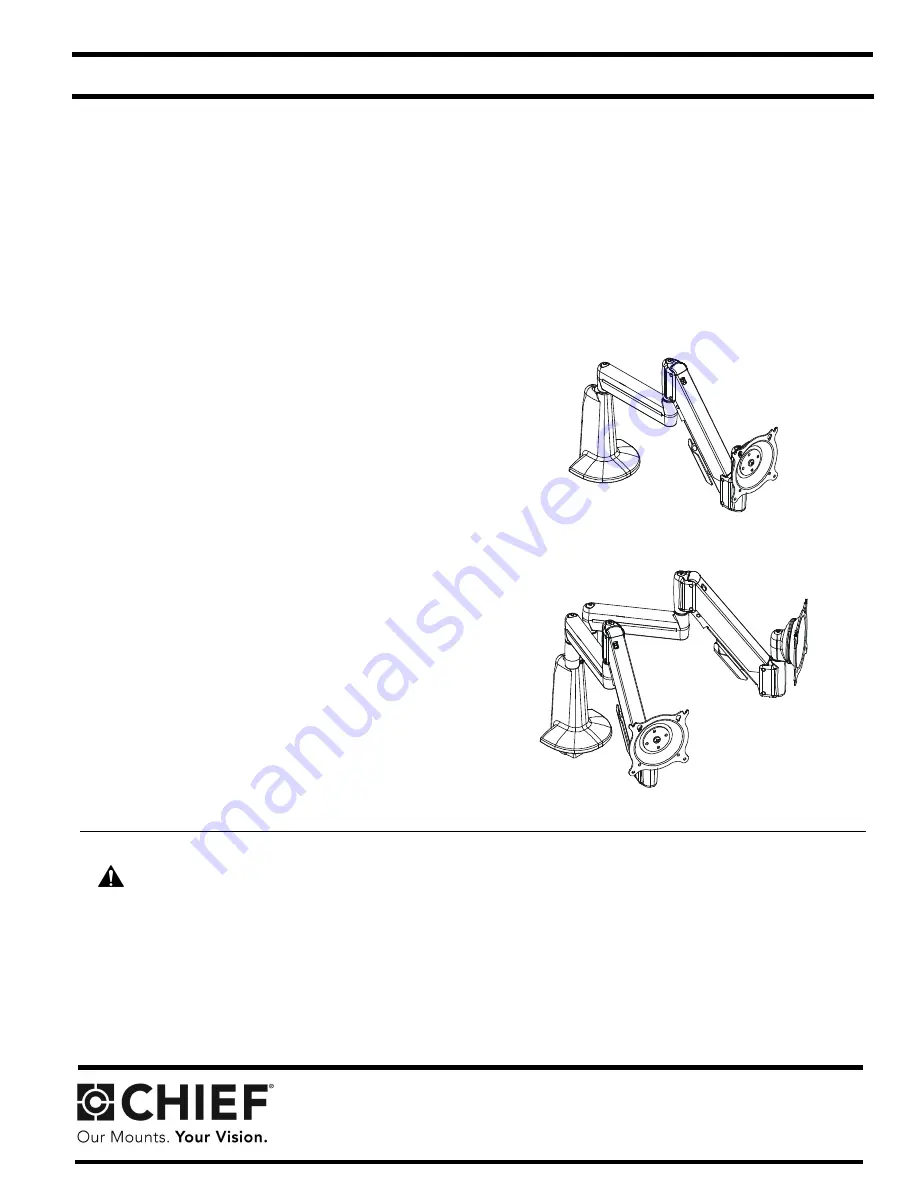
MSP-TDKCG110
(Dual Arm - Height Adjustable)
MSP-TDKCY220
(Multi-Dual Arm - Height Adjustable)
WARNING:
It is the installer’s responsibility to make sure all components are properly assembled and installed
using the instructions provided. Failure to read, thoroughly understand, and follow all instructions can result in
serious personal injury, damage to equipment, or voiding of factory warranty.
•
If you have any questions about this these instructions or your specific installation, contact Chief Manufacturing
at 1-800-582-6480 or 952-894-6280.
Chief® and Centris™ are registered trademarks of Milestone AV Technologies, Inc. All rights reserved.


