background image

Installation Instructions

Models: MSP-TDKCG110 & MSP-TDKCY220

5

MOUNT INSTALLATION

Two installation options exist:

Edge Installation

Grommet (Hole) Installation; requires 3/8" to 3"
diameter hole and access to the bottom of the
desk

ASSEMBLY

1.

Determine approximate location for mount keeping in
mind display size, arm extension, height adjustment
(if applicable), and pitch/roll requirements.

2.

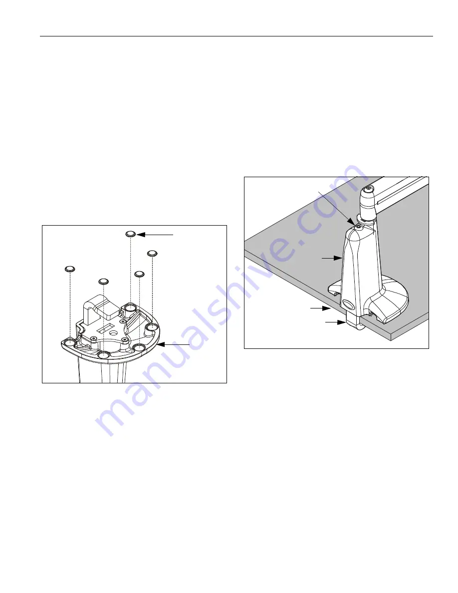
Peel backing from adhesive bumpers (40) and attach
to bottom of mount (10 or 20, as applicable) (See
Figure 2).

NOTE:

One extra bumper (40) included for convenience.

Figure 2:  Install Bumpers

3.

Proceed to Edge Installation, or Grommet (Hole)
Installation, as desired.

EDGE INSTALLATION

IMPORTANT ! :

IF your display has a recessed mounting

hole cavity,

and

 the Centris bracket will not fit into that

cavity (See Figure 11), THEN proceed to "DISPLAY
INSTALLATION" (See Page 9)

before continuing

 with the

Edge Installation procedure.  Otherwise, continue below.

1.

Slip mount (10 or 20, as applicable) over edge of desk
so that clamp fully contacts desk edge.  Using hex key
(210), securely tighten clamp adjustment screw (See
Figure 3).

NOTE:

Bracket (50) and one screw (60) not used in this

installation.

Figure 3:  Edge Installation

2.

Proceed to:

"CABLE MANAGEMENT" if you have an MSP-
TDKCG110 mount

and

 your display

was

previously

 installed, or to

"DISPLAY INSTALLATION" if you have an MSP-
TDKCG110 mount

and

 your display

was not

previously installed, or to

"MULTI-DUAL ARM ASSEMBLY" if you have an
MSP-TDKCY220 mount.

10 or 20

40
(5 places)

Edge of Desk

Clamp

10 shown;

Clamp Adjustment
Screw

20 similar

Summary of Contents for MSP-TDKCG110

Page 1: ... IMPORTANT WARNINGS AND CAUTIONS on page 2 for weight capacities of these mounts MSP TDKCG110 Dual Arm Height Adjustable MSP TDKCY220 Multi Dual Arm Height Adjustable WARNING It is the installer s responsibility to make sure all components are properly assembled and installed using the instructions provided Failure to read thoroughly understand and follow all instructions can result in serious per...

Page 2: ...g the component WARNING Exceeding the weight capacity can result in serious personal injury or damage to equipment MSP TDKCG110 It is the installer s responsibility to make sure the combined weight of all components attached to the mount including the display does not exceed 25 lbs 11 kg MSP TDKCY220 It is the installer s responsibility to make sure the combined weight of all components attached t...

Page 3: ...Installation Instructions Models MSP TDKCG110 MSP TDKCY220 3 DIMENSIONS MSP TDKCG110 DIMENSIONS MSP TDKCY220 ...

Page 4: ... 40 BUMPER Adhesive 6 50 BRACKET Grommet 1 60 SCREW Button Head Cap 5 16 18 x 4 See Note Below 70 WASHER 5 16 UHMW plastic MSP TDKCY220 only 2 80 WASHER 5 16 Stainless Steel MSP TDKCY220 only 4 90 PIN MSP TDKCY220 only 2 100 SPACER UHMW plastic MSP TDKCY220 only 2 110 WASHER Lock External Tooth 5 8 MSP TDKCY220 only 4 120 NUT Nylok 5 16 18 MSP TDKCY220 only 2 130 SCREW Phillips Pan Machine M4 x 10...

Page 5: ...IF your display has a recessed mounting hole cavity and the Centris bracket will not fit into that cavity See Figure 11 THEN proceed to DISPLAY INSTALLATION See Page 9 before continuing with the Edge Installation procedure Otherwise continue below 1 Slip mount 10 or 20 as applicable over edge of desk so that clamp fully contacts desk edge Using hex key 210 securely tighten clamp adjustment screw S...

Page 6: ...ore continuing with the Grommet Installation procedure Otherwise continue below 4 From below desk insert retained clamp attach screw and washer through bracket 50 and up through hole in desk See Figure 6 Using hex key 210 thread screw into baseplate nut Do not tighten screw at this time Figure 6 Grommet Hole Installation 5 From above desk center mount 10 or 20 as applicable over hole 6 From below ...

Page 7: ...Y connector into nut 120 See Figure 7 Do not tighten screw 60 at this time CAUTION Improper positioning of arm assembly 30 may result in failure of mount and subsequent damage to displays Do NOT position either arm assembly 30 in gray shaded area 5 Position arm assembly 30 within UNSHADED area as shown See Figure 8 Using hex key 210 tighten screw 60 as required to maintain position Figure 8 Allowa...

Page 8: ... and washers may remain in outer mount arm assembly Figure 9 Multi Dual Arm Modification 2 Lift outer mount arm assembly from pin with screw and washers and place on protective surface 3 Remove spacer from pin See Figure 9 4 Install washer 110 on pin See Figure 9 5 Re install outer mount arm assembly with screw and washers on pin See Figure 9 6 Insert and hold nut in lower bore of inner mount arm ...

Page 9: ...not fit into that cavity See Figure 11 1 Carefully place display face down on protective surface 2 Place four spacers 150 over each of the mount holes on the back of the display See Figure 11 Figure 11 Install Spacers and Screws 3 Pick up and orient the mount 10 or arm assembly 30 as applicable so that the mounting holes in the Centris bracket are aligned with the holes in the spacers 150 See Figu...

Page 10: ... upper mounting holes on the display See Figure 12 Thread screws completely into display then back out 3 1 2 turns Figure 12 Install Upper Screws and Display 2 Pick up and align display so that screws 130 installed in previous step fit into the upper 100mm x 100mm mounting cutouts or upper 75mm x 75mm mounting holes as applicable in Centris bracket See Figure 12 Lower display firmly into place NOT...

Page 11: ...y sliding it back towards the centerline of the arm See Figure 14 NOTE If necessary cable management bracket attach screws may be tightened using hex key 180 CAUTION Ensure that adequate cable slack exists for movement of display and that cables will not be pinched by installation of cover 90 or screws 80 5 Carefully insert cables in cavity located in lower portion of mount arm See Figure 16 6 Usi...

Page 12: ...ustment screw s as necessary See Figure 18 Figure 18 Pivot Swing Adjustment HEIGHT ADJUSTABLE 1 Using key 200 slightly loosen or tighten the adjustment screw as necessary See Figure 19 If display settles on its own then rotate adjustment screw counterclockwise towards the symbol If display rises on its own then rotate adjustment screw clockwise towards the symbol NOTE It may be necessary to raise ...

Reviews: