background image

Installation Instructions

4

4.

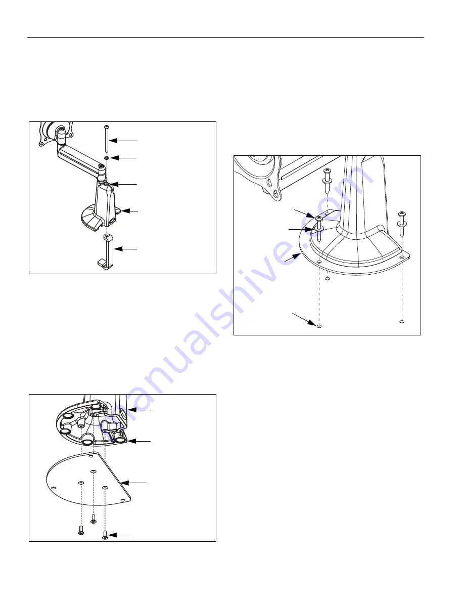
Remove clamp attach screw, washer, and clamp from
desk mount housing (See Figure 4).

NOTE:

Clamp attach screw, washer, and clamp will not

be reused in MSP-DARAC1B installation.
However, if desired, attach screw can be inserted
in bore for appearance only.

Figure 4:  Remove Clamp

BRACKET INSTALLATION

1.

Using Phillips screwdriver, install bracket (10) to desk
mount  housing with three screws (40) (See Figure 5).
Tighten securely.

NOTE:

If desired, adhesive pads can remain installed on
bottom of desk mount housing.

Figure 5:  Install Bracket

MOUNT INSTALLATION

1.

Determine approximate location for mount keeping in
mind display size, arm extension, and pitch/roll
requirements.

2.

Using bracket (10) as a template, mark location of
three pilot holes.

3.

Drill three 1/8" diameter pilot holes in mounting
structure at locations marked in previous step (See
Figure 6).  Ensure pilot holes are straight.

Figure 6:  Install Mount

IMPORTANT ! :

IF you will be installing a display with

RECESSED mounting holes, then install display to
mount

before continuing

 with this mount installation

procedure.  Proceed to DISPLAY INSTALLATION
section of Desk Mount Installation Instructions.

4.

Using Phillips screwdriver, install screws (20) through
washers (30) and mount (10) into pilot holes (See
Figure 6).  Tighten securely.

5.

Refer to Desk Mount Installation Instructions for
DISPLAY INSTALLATION (for display with

flush

mounting holes), CABLE MANAGEMENT, and
ADJUSTMENT.

Clamp attach screw

Washer

Clamp

Bore

Desk mount housing

10

40 (3 places)

Desk mount
housing

Adhesive Pads
(5 places)

20 (3 places)

30 (3 places)

10

Pilot holes
(3 places)

Summary of Contents for MSP-DARAC1B

Page 1: ...ion of KCS 110 mount Weight capacity of 40 lbs 18 kg MSP DARAC1B Shown installed on KCS 110 purchased separately WARNING It is the installer s responsibility to make sure all components are properly assembled and installed using the instructions provided Failure to read thoroughly understand and follow all instructions can result in serious personal injury damage to equipment or voiding of factory...

Page 2: ...aller s responsibility to make sure the structure to which this component is attached can support five times the combined weight of all equipment Reinforce the structure as required before installing the component WARNING Exceeding the weight capacity can result in serious personal injury or damage to equipment It is the installer s responsibility to make sure the combined weight of all components...

Page 3: ...splay See instructions included with desk mount 2 If previously attached loosen clamp attach screw See Figure 2 Remove desk mount from desk Figure 2 Remove Desk Mount 3 Using 2 5mm hex key remove base plate and attach screws from desk mount housing See Figure 3 NOTE Base plate and attach screws will not be reused in MSP DARAC1B installation Figure 3 Remove Base Plate Table 1 Parts Item Description...

Page 4: ...ket 10 as a template mark location of three pilot holes 3 Drill three 1 8 diameter pilot holes in mounting structure at locations marked in previous step See Figure 6 Ensure pilot holes are straight Figure 6 Install Mount IMPORTANT IF you will be installing a display with RECESSED mounting holes then install display to mount before continuing with this mount installation procedure Proceed to DISPL...

Reviews: