background image

I N S T A L L A T I O N   I N S T R U C T I O N S
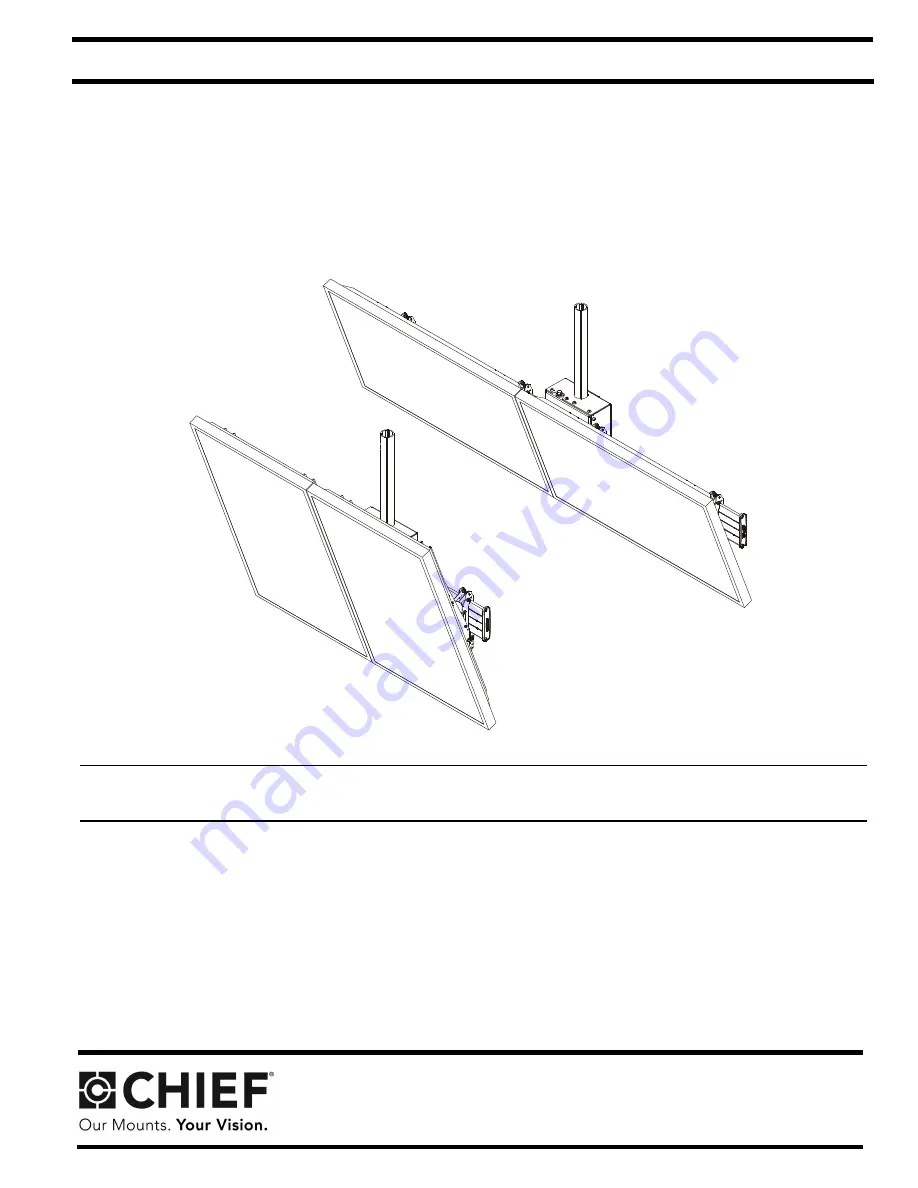
LCM2X1U

LCM2X1UP

Ceiling-Mounted Menu Boards

Spanish Product Description
German Product Description

 Portuguese Product Description

 Italian Product Description

Dutch Product Description

French Product Description

LCM2X1U / LCM2X1UP

Summary of Contents for LCM2X1U

Page 1: ... T I O N S LCM2X1U LCM2X1UP Ceiling Mounted Menu Boards Spanish Product Description German Product Description Portuguese Product Description Italian Product Description Dutch Product Description French Product Description LCM2X1U LCM2X1UP ...

Page 2: ...ructions can result in serious personal injury damage to equipment or voiding of factory warranty It is the installer s responsibility to make sure all mounting systems are properly assembled and installed using the instructions provided WARNING Failure to provide adequate structural strength for this mounting system can result in serious personal injury or damage to equipment It is the installer ...

Page 3: ...Installation Instructions LCM2X1U LCM2X1UP 3 DIMENSIONS 1 16 29 4 COLUMN SOLD SEPARATELY 8 58 217 8 DIMENSIONS INCHES MILLIMETERS LCM2X1U DIMENSIONS INCHES MILLIMETERS LCM2X1U 1 83 46 6 ...

Page 4: ...LCM2X1U LCM2X1UP Installation Instructions 4 0 13 3 2 23 62 600 0 400mm Mounting Pattern 600mm Mounting Pattern LCM2X1U LCM2X1U DIMENSIONS INCHES MILLIMETERS DIMENSIONS INCHES MILLIMETERS ...

Page 5: ...Installation Instructions LCM2X1U LCM2X1UP 5 DIMENSIONS cont d 31 50 800 0 800mm Mounting Pattern LCM2X1U LCM2X1UP 1 16 29 4 SEPARATELY DIMENSIONS INCHES MILLIMETERS DIMENSIONS INCHES MILLIMETERS ...

Page 6: ...M2X1U LCM2X1UP Installation Instructions 6 DIMENSIONS cont d 32 50 825 5 TILT RANGE 5 TO 20 15 75 400 0 LCM2X1UP 400mm Mounting Pattern LCM2X1UP DIMENSIONS INCHES MILLIMETERS DIMENSIONS INCHES MILLIMETERS ...

Page 7: ...sel Chave de bocas Chiave a punte aperte Steeksleutel Clé à fourche By Hand A mano Von Hand Com a mão A mano Met de hand À la main Hex Head Wrench Llave de cabeza hexagonal Sechskantschlüssel Chave de cabeça sextavada Chiave esagonale Zeskantsleutel Clé à tête hexagonale Pencil Mark Marcar con lápiz Stiftmarkierung Marcar com lápis Segno a matita Potloodmerkteken Marquage au crayon Drill Hole Perf...

Page 8: ...x20mm L 4 M 8 Nesting spacer N 4 Universal washer Q 1 3 32 S 1 5 32 R 3 1 8 T 1 10 24 x 1 4 U 2 5 16 x 1 V 2 W 3 5 16 x 3 4 AA 1 BB 1 Bottom coupling 5 16 Bottom stop collar Used with CPA Series extension column system Used with 1 1 2 NPT column system Z 4 10 24 CC 1 Ceiling mount assembly LCM2X1UP OR DD 1 Back cover EE 4 Interface bracket LCM2X1UP OR EE 4 Interface bracket LCM2X1U X 4 10 24 x 2 1...

Page 9: ...AUTION WATCH FOR PINCH POINTS Do not place fingers between moveable parts 1 Insert two 5 16 x 3 4 set screws W into back of ceiling mount CC See Figure 1 Figure 1 2 Slide ceiling mount CC up from below onto installed column not included See Figure 2 3 Tighten two 5 16 set screws installed in Step 1 against column 4 Thread bottom coupling BB onto installed column until tight with a minimum of four ...

Page 10: ...g up holes in collar with holes in column Figure 5 5 Install two 5 16 x 1 self tapping screws U through two 5 16 flat washers V bottom stop collar AA and into installed column See Figure 5 6 Install and tighten 5 16 x 3 4 set screw W into bottom stop collar AA See Figure 5 7 Loosen two installed set screws W and slide ceiling mount down extension column until it rests on the bottom stop collar AA ...

Page 11: ...quire a washer Use the universal washer N only with M4 M5 and M6 screws NOTE The nesting spacers M may be used separately or put two together in different configurations to create different size spacers See Figure 9 Figure 9 Attaching Display to Ceiling Mount WARNING IMPROPER INSTALLATION CAN LEAD TO DISPLAY FALLING CAUSING SERIOUS PERSONAL INJURY OR DAMAGE TO EQUIPMENT The displays MUST be locate...

Page 12: ...3 roll each direction 1 Turn the roll adjustment bolt in the direction necessary for the desired roll See Figure 12 2 Stop adjusting when the desired setting is reached Figure 12 Tilt The interface brackets allow 5 to 20 tilt and can be locked at 0 10 and 20 tilt 3 If necessary loosen button head tilt friction bolt located on side of interface bracket See Figure 13 4 Adjust tilt as required See Fi...

Page 13: ... OPTIONAL Security 1 OPTIONAL Add padlock not included to each interface bracket to lock display to ceiling mount See Figure 14 Figure 14 2 Install back cover DD into four holes on back of ceiling mount See Figure 15 Figure 15 Padlock Optional DD ...

Page 14: ...LCM2X1U LCM2X1UP Installation Instructions 14 ...

Page 15: ...Installation Instructions LCM2X1U LCM2X1UP 15 ...

Page 16: ...894 6918 Europe A Franklinstraat 14 6003 DK Weert Netherlands P 31 0 495 580 852 F 31 0 495 580 845 Asia Pacific A Office No 918 on 9 F Shatin Galleria 18 24 Shan Mei Street Fotan Shatin Hong Kong P 852 2145 4099 F 852 2145 4477 Chief a products division of Milestone AV Technologies 8800 003036 Rev00 2018 Milestone AV Technologies www milestone com 04 18 ...

Reviews: