background image

Model: K-Series

Installation Instructions

8

DISPLAY INSTALLATION

SINGLE DISPLAY AND KCY-210/-220

NOTE:

If you are installing DUAL / TRIPLE displays

(Except KCY-210/-220), then proceed to page 9.

The mounting holes on the back of your display will either
be

flush with

 the back surface, or

recessed into

 the back

surface.  Refer to the applicable installation procedure.

FLUSH MOUNTING HOLES

1.

Verify that you have the following parts:

CAUTION:

Using screws of improper size may

damage your display!  Proper screws will easily and
completely thread into display mounting holes.

CAUTION:

Inadequate thread engagement in display

may cause display to fall!  Back out screws ONLY as
necessary to allow installation of Centris bracket!

2.

Ensure Centris bracket is able to swivel and tilt easily,
yet still be tight enough to hold display in desired
position.  Adjust as required before proceeding.  See
"ADJUSTMENT" for detail.

3.

Using Phillips screwdriver, carefully install two screws
(20) into the

upper

 mounting holes on the display.

Thread screws completely into display, then back out
3 complete turns.

4.

Pick up and align display so that screws (20) (installed
on the back of the display in the previous step) fit into
the mounting holes on the Centris bracket; rotate the
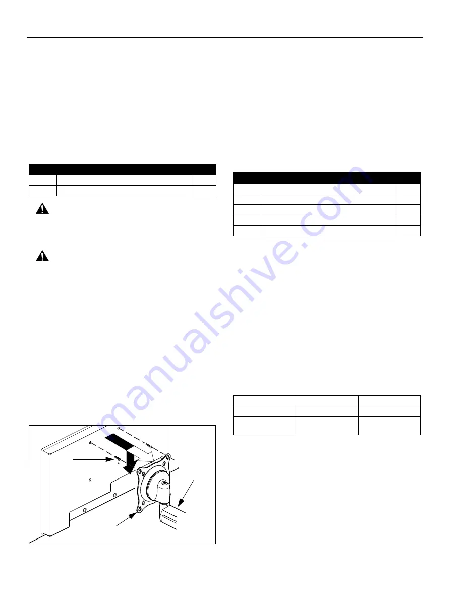
bracket as required (See Figure 11).  Lower the
display firmly into place.

Figure 11:  Single Display - Flush Mount

5.

Using Phillips screwdriver, install two remaining
screws (20) through the

lower

 mounting holes in

Centris bracket into the display.

6.

Tighten all four screws (20).  Do not overtighten!

7.

KCY-210/-220 Only: Repeat Steps 1-6 for second
display.

8.

Proceed to "CABLE MANAGEMENT."

RECESSED MOUNTING HOLES

1.

Verify that you have the following parts:

2.

Ensure Centris bracket is able to swivel and tilt easily,
yet still be tight enough to hold display in desired
position.  Adjust as required before proceeding.  See
"ADJUSTMENT" for detail.

3.

Carefully place display face down on protective
surface.

4.

Determine depth of recessed mounting holes relative
to back surface of display (against which Centris head
will contact).

5.

Select proper length spacer and screw from table
below:

NOTE:

All spacers used should be the same length.  If

the recess depths result in multiple spacer
lengths, then select the longer spacer.

6.

Place the four selected spacers over each of the
mount holes on the back of the display.

7.

Pick up and orient the mount (10) so that the
mounting holes in the Centris bracket are aligned with
the holes in the spacers; rotate the bracket as
required (See Figure 12).

Item

Description

Qty

10

MOUNT, K-Series

1

20

SCREW, Phillips Pan Machine, M4 x 12mm

4

10

20
(2 places)

Centris Bracket

Item

Description

Qty

10

MOUNT, K-Series

1

20

SCREW, Phillips Pan Machine, M4 x 20mm

4

30

SCREW, Phillips Pan Machine, M4 x 30mm

4

40

SPACER, Nylon, 3/8" long

4

50

SPACER, Nylon, 3/4" long

4

IF recess DEPTH is: THEN use spacer:

AND screw:

3/8" or less

40 (3/8" long)

20 (M4 x 20mm)

More than 3/8" up to
and including 3/4"

50 (3/4" long)

30 (M4 x 30mm)

Summary of Contents for K Series

Page 1: ...overs most of the K Series wall desk and pole mounts for single dual and triple displays In addition this Instruction Manual also covers selected K Series accessories NOTE Some K Series mounts such as Extreme Tilt Grommet and Table as well as most K Series accessories have separate Instruction Manuals See Specifications for a complete list of models covered by this Instruction Manual NOTE If an ac...

Page 2: ... result in serious personal injury damage to equipment or voiding of factory warranty It is the installer s responsibility to make sure all components are properly assembled and installed using the instructions provided WARNING Failure to provide adequate structural strength for this component can result in serious personal injury or damage to equipment It is the installer s responsibility to make...

Page 3: ...MANAGEMENT 12 ADJUSTMENT 13 TOOLS REQUIRED FOR INSTALLATION Phillips Screwdriver 1 and 2 9 16 Wrench KSA 1015 1016 Only Drill All Wall Mounts 1 8 Drill Bit All Wall Mounts except KSA 1015 1016 1 4 Drill Bit KSA 1015 1016 Only 2 5mm Hex Key approximately 3 32 provided with Desk Mounts 5 32 Hex Key provided with applicable K Series mounts 3 16 Hex Key provided with all K Series mounts NOTE Other too...

Page 4: ...le Yes 16 5 2 2 25 KPV 110 Single Pole Single Yes 13 3 2 2 25 KWD 130 Single Wall Single Yes 18 6 5 1 25 KWS 220 Dual Wall Single No 13 5 6 4 17 KWD 220 Dual Wall Dual No 20 6 4 17 KCS 220 Dual Desk Single No 14 6 4 40 KCD 220 Dual Desk Dual No 20 5 6 4 17 KCY 210 Dual Desk Multi Dual Yes one arm 20 2 2 20 KCY 220 Dual Desk Multi Dual Yes two arms 20 2 2 20 KWD 230 Dual Wall Single No 18 6 5 9 40 ...

Page 5: ...ket 20 to compress into soft wall surface resulting in difficult mount installation or improper engaging of set screw in step 6 IMPORTANT IF you will be installing a SINGLE display with RECESSED mounting holes then proceed to DISPLAY INSTALLATION before continuing with this mount installation procedure 5 Insert top of mount 10 over lip on top of bracket 20 See Figure 2 Swing mount 10 down flush ag...

Page 6: ...re not used in this installation 1 Slip mount 10 over edge of desk so that clamp fully contacts desk edge Using 3 16 hex key securely tighten clamp adjustment screw See Figure 5 Figure 5 Desk Mount Edge Installation 2 If you are installing SINGLE display with RECESSED mounting holes Proceed to CABLE MANAGEMENT KCY 210 220 Proceed to MULTI DUAL ARM ASSEMBLY ALL other display configurations Proceed ...

Page 7: ...urations Proceed to DISPLAY INSTALLATION INSTALLATION TO POLE 1 Verify that you have the following parts IMPORTANT IF you will be installing a SINGLE display with RECESSED mounting holes then proceed to DISPLAY INSTALLATION before continuing with this mount installation procedure 2 Determine approximate location for mount keeping in mind display size extension height adjustment if applicable and p...

Page 8: ...ewdriver install two remaining screws 20 through the lower mounting holes in Centris bracket into the display 6 Tighten all four screws 20 Do not overtighten 7 KCY 210 220 Only Repeat Steps 1 6 for second display 8 Proceed to CABLE MANAGEMENT RECESSED MOUNTING HOLES 1 Verify that you have the following parts 2 Ensure Centris bracket is able to swivel and tilt easily yet still be tight enough to ho...

Page 9: ...ris bracket into the display See Figure 13 Tighten all four screws 20 Do not overtighten Figure 13 Dual Triple Display Flush Mount 5 Proceed to ARRAY ASSEMBLY RECESSED MOUNTING HOLES 1 Verify that you have the following parts 2 Carefully place display face down on protective surface 3 Determine depth of recessed mounting holes relative to back surface of display against which Centris head dual kno...

Page 10: ...e through washer 50 washer 40 washer 50 array 10 array mount arm assembly and into nut 100 See Figure 15 Tighten screw as required using 3 16 hex key 6 Slide the Centris head dual knob assembly onto the array 10 See Figure 16 Ensure both the top and the bottoms of the Centris head are engaged into the corresponding slots in the array 10 Figure 16 Install Display 7 Position the displays as desired ...

Page 11: ...e Figure 18 5 While holding nut 90 in lower bore of Y connector insert screw 30 through washer 50 washer 40 washer 50 arm assembly 10 and Y connector into nut 90 See Figure 18 Loosely install screw 30 using 3 16 hex key CAUTION Improper positioning of arm assembly 10 may result in failure of mount and subsequent damage to displays Do NOT position either arm assembly 10 in gray shaded area 6 Positi...

Page 12: ...and place on protective surface 3 Remove spacer from pin See Figure 20 4 Install washer 80 on pin See Figure 20 5 Re install outer arm with screw and washers on pin See Figure 20 6 Insert and hold nut in lower bore of inner arm See Figure 20 7 Tighten screw as required using 3 16 hex key See Figure 20 8 Proceed to CABLE MANAGEMENT for display with RECESSED mounting holes or to DISPLAY INSTALLATION...

Page 13: ...5 Carefully insert cables in cavity located in lower portion of static mount arm See Figure 23 6 Using Phillips screwdriver install cover 10 with two screws 20 Figure 23 Static Arm Cable Path NOTE Installation is complete NOTE Cable ties provided with certain models may be used for additional cable management capability ADJUSTMENT ARM PIVOT SWING CAUTION If washer 80 has been used to assemble KCY ...

Page 14: ...ew Figure 25 Height Adjustable Arm Adjustment CENTRIS HEAD SINGLE DISPLAY AND KCY 210 220 1 If previously attached disconnect cables from display then remove display 2 Using Phillips screwdriver slightly loosen or tighten the adjustment screw as necessary See Figure 26 Figure 26 Single Display Adjustment 3 Install mount and then display cables See DISPLAY INSTALLATION DUAL TRIPLE DISPLAY 1 LATERAL...

Page 15: ...Installation Instructions Model K Series 15 ...

Page 16: ...Model K Series Installation Instructions 16 ...

Reviews: