background image

Flat Panel
Dual Swing Arm Wall Mount
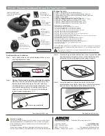
FWD-111

The FWD-111 dual arm wall mount was designed to support 
flat panel displays with 10” to 30” diagonal screens and  
weighing a maximum of 40 lbs (18.1 kg).

At only 2.15” deep in the closed position, the mount allows 
side-to-side pivot adjustment up to 180 degrees in the closed 
and the fully extended position. A display can be extended 
14.2” from the wall and pivot 360 degrees.

The FWD-111 fits the following VESA® patterns:

75mm/75mm (using the Centris™ mount)

100mm/100mm (using the Centris mount)

200mm/100mm (using the interface bracket with the 
Centris mount)

BEFORE YOU BEGIN                                                                         

Caution:  To prevent damage to the FWD-111, which could affect or void the Factory warranty, and to the 
equipment that will be attached to it, thoroughly study all instructions and illustrations before you begin 
the installation.  Pay particular attention to the “Important Warnings and Cautions” on Page 2.

The maximum weight to be installed on the FWD-111 wall mount is 40 pounds (18.1 kg).

The FWD-111 wall mount is designed to be installed using wall studs or supporting framework.  The structure to 
which the FWD-111 wall mount is anchored must be capable of supporting 

five times

 the total weight of the mount 

and all attached equipment.

If you have any questions about this installation, contact Chief Manufacturing at 1-800-582-6480.

I N S T A L L A T I O N   I N S T R U C T I O N S

CHIEF MANUFACTURING INC.

1-800-582-6480

  952-894-6280  FAX 952-894-6918

8401 EAGLE CREEK PARKWAY STE. 700
SAVAGE, MINNESOTA 55378  USA

PART NO. 8832-000132

©

2005 Chief Manufacturing

www.chiefmfg.com

10/05

Summary of Contents for FWD-111

Page 1: ...arranty and to the equipment that will be attached to it thoroughly study all instructions and illustrations before you begin the installation Pay particular attention to the Important Warnings and Ca...

Page 2: ...WD 111 WARNING Be aware also of the potential for personal injury or damage to the unit if it is not adequately mounted WARNING The installer is responsible for verifying that the wall to which the FW...

Page 3: ...d method of installation INSPECT THE UNIT BEFORE INSTALLING WARNING Watch for pinch points Do not put your fin gers between movable parts 1 Carefully inspect the FWD 111 for shipping damage If any dam...

Page 4: ...4 Installation Instructions FWD 111 COMPONENTS 10 140 120 80 100 70 130 30 20 110 150 160 40 90 50 60 Figure 1 FWD 111 Components...

Page 5: ...LLIPS FLAT HEAD MACHINE SCREW M4 x 12mm 6 90 PHILLIPS PAN HEAD MACHINE SCREW M4 x 5mm 4 100 PHILLIPS PAN WOOD SCREW 10 x 2 1 2 2 SINGLE STUD MOUNTED 110 WASHER 2 120 WALL BRACKET 1 130 COVER PLATE 2 C...

Page 6: ...If not reinforce the struc ture before installing the FWD 111 2 Using the wall bracket 120 as a template drill two 3 32 pilot holes to a minimum depth of 1 1 2 3 Using two 10 x 2 1 2 wood screws 100 a...

Page 7: ...111 over the bottom of the wall bracket see Figure 5 2 Using the 5 32 hex wrench 160 secure the FWD 111 to the wall bracket by tightening the set screw see Figure 6 NOTE Refer to the INTRODUCTION on p...

Page 8: ...ons 30 with 40 or 50 with 60 CAUTION If your display uses a screw size other than M4 X 20mm or M4 X 30mm DO NOT use the M4 X 20mm or M4 X 30mm screws Using the wrong screws could result in damage to y...

Page 9: ...rom the two screws started in Step 2 4 Install the remaining two M4 x 5mm Phillips pan head screws 90 into the bottom two mounting holes of the dis play 5 Secure the display to the mount by tightening...

Page 10: ...wear Rotational Tilt Pitch and Roll Adjustment 1 Test the Centris adjustment by tilting pitching and rolling the Centris mount interface see Figure 12 2 If necessary remove display from the mount 3 U...

Page 11: ......

Page 12: ......

Reviews: