background image

Part no 

Issue no 

Series no 

Date 

Page 

8940173703


01 

09/2015


8/12 

CP3850

 SERVICE

MANUAL 

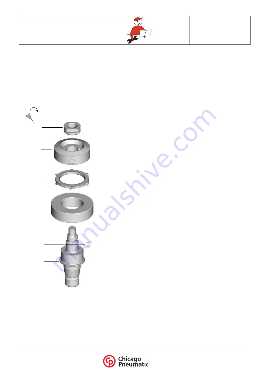
Shaft unit 

Di smantling the shaft unit 

1. Remove  the  safety  screw  using  the  provided  allen  key  and

locking the output shaft with the stop finger

2. Unscrew  the  front  flange  using  the  provided  pin  spanner  and

locking  the  output  shaft  with  the  stop  finger,    then  remove  the

grinding wheel

3. Tighten the  front  flange of  2 turns  on the shaft and remove the

autobalancer taking the tool in the  hand slam and taping with a

mallet on the end of the shaft and on the front flange

4. Clamp  the  head/housing  of  the  tool  in  a  vice.  Ensure  the  stop

finger is not clamped

5. Unscrew the 3 screws CHc M5x12 and remove the washers and

the guard

6. Unscrew the ring screw (R/H thread)

7. Remove the tool from the vice

8. Using a mallet, tap on the housing to slide out the shaft unit

9. Unscrew the nut (R/H thread)

10. Using an extractor, remove the bevel gear and the deflector

11. Using an extractor, remove the bearing

Reassembling the shaft unit 

1. Position  the  new  bearing  onto  the  spindle  and  press  it  into

position

2. Press the parallel key

3. Place the deflector onto the new bevel gear

4. Position the bevel gear onto the output shaft

5. Apply a drop of LOCTITE 243 on the first thread of the shaft and

tighten the nut (R/H thread 25 Nm)

6. Apply the recommended quantity of grease, réf. 6159901480 (19

ml), onto the shaft bevel gear

7. Clamp horizontally the head/housing of the tool in a vice. Ensure

the stop finger is not clamped

8. Slide the  output shaft into the  housing  and  fit it into the  needle

bearing taping carefully with a mallet.  Check the output  for  free

rotation

9. Apply a drop of LOCTITE 243 on the first ring screw thread (R/H

thread 45 Nm)

10. Place the guard onto the housing  and tighten the 3  screws CHc

M5x12 (R/H thread 5 Nm) with there washer

11. Place the autobalancer on the output shaft

12. Place  a  new  grinding  wheel  and  screw  on  the  front  flange  with

the provided pin spanner

13. Tighten the safety screw with the provided Allen key

14. Test the tool to make sure it works properly

Bearing 

Nut 

Bevel gear 

Déflector 

Output spindle 

Parallel key 

25 Nm 

LOCTITE 243 

Summary of Contents for CP3850 SERIES

Page 1: ...CP Technocenter 38 rue Bobby Sands BP10273 44800 Saint Herblain France Part no Issue no Series no Date Page 8940173703 01 C 09 2015 1 12 www cp com CP3850 SERVICE MANUAL ...

Page 2: ...t more than 6 3bar 90psi Basic Safe Working Practices Make sure that the workbench is clear and free from fluids small parts rags and cleaning materials remaining from a previous task Excess hose dangling from the bench or lying on floor represents a potential tri p slip fall hazard Do not smoke anywhere near the workbench Beware of noise hazards Using an air blow gun to clear small passages in co...

Page 3: ...rwise the parts may not be ordered correctly alpha code letter at the beginning of the serial number Rotor blades in grinder tools some Chicago Pneumatic tools have rotor blades having a PTFE content Such tools can be identified by referring to the tool service sheet It is important to observe the warning printed in the service instructions concerning the handling of such material Ensure that the ...

Page 4: ...g Spring Valve Partition Screw Motor complete see p 06 Housing Output shaft complete see p 08 Ring screw Autobalancer Front flange Safety screw Grinding wheel Guard Washer Screw Screw Handle bracket Rotating spacer Washer Screw Rotating exhaust 3 5 Nm 0 5 Nm Loctite 222 45 Nm Loctite 243 Exploded view of the tool 5 Nm ...

Page 5: ...orizontally the head housing of the tool in a vice Ensure the stop finger is not clamped 2 Slide the output shaft into the housing and fit it into the needle bearing taping carefully with a mallet Check the output for free rotation 3 Apply a drop of LOCTITE 243 on the first ring screw thread R H thread 45 Nm 4 Place the guard onto the housing and tighten the 3 screws CHc M5x12 R H thread 5 Nm with...

Page 6: ...850 SERVICE MANUAL Motor unit Rear end plate Blade Front end plate O ring Pinion Bearing Spacer Needle Cylinder Spigot Rotor Bearing Regulator LOCTITE 243 Piston Regulator housing O ring Screw O ring Spring washer Overspeed valve Spring Pin Spirol 10 Nm 12 Nm LOCTITE 243 ...

Page 7: ...n on the inner race 5 Apply a drop of LOCTITE 243 on the first thread of the pinion and tighten it on the rotor R H thread 10 Nm 6 Turn the motor unit over held by the drive gear in the vice 7 Fit 4 new blades into the rotor slots 8 Place the cylinder on the rotor ensure correct orientation of the cylinder plate on plate with the pin hole on the top 9 Position the rear end plate onto the cylinder ...

Page 8: ... the bearing Reassembling the shaft unit 1 Position the new bearing onto the spindle and press it into position 2 Press the parallel key 3 Place the deflector onto the new bevel gear 4 Position the bevel gear onto the output shaft 5 Apply a drop of LOCTITE 243 on the first thread of the shaft and tighten the nut R H thread 25 Nm 6 Apply the recommended quantity of grease réf 6159901480 19 ml onto ...

Page 9: ...Part no Issue no Series no Date Page 8940173703 01 C 09 2015 9 12 CP3850 SERVICE MANUAL ...

Page 10: ...ate Page 8940173703 01 C 09 2015 10 12 CP3850 SERVICE MANUAL Handle complete Handle Bushing inlet O ring Screen Spring conical Ball Ball chair Spring cylindrical Needle Lever Latch lever Spring Grooved pin Ball Inlet bushing 60 Nm ...

Page 11: ... vice with protection 2 Place the latch lever and his spring into the handle then fit the smallest of the 2 grooved pin with a hammer and a drift punch 3 Place the lever into the handle then fit the longgest of the 2 grooved pin with a hammer and a drift punch 4 Remove the handle from the vice 5 Slide the needle by the back of the handle until it comes in contact with the lever fit the spring on t...

Page 12: ...m 6500 rpm 6500 rpm 6000 rpm Copyright 2015 Chicago Pneumatic Tool Co LLC All rights reserved Any unauthorised use or copy of the contents herein whether in part or in full is prohibited This particularly applies to trademarks brand names part numbers and drawings Only genuine parts used Warranty or Product Liability does not cover any damages or malfunction due to the use of unauthorised parts CP...

Reviews: