


Page 10
SKU 94678
for technical questions, please call 1-800-444-3353.
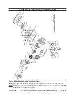
Generator control illustrations
on/off
switch (52a)
circuit
protectors
dc (59a) ac (53a)
pilot lamp
(56a)
dipstick
(28)
Voltmeter
(58a)
Grounding
point (55a)
ac outlets
(54a)
battery charging
outlet (57a)
choke
control (80)
recoil start
Handle (64)
fuel Valves
(9a, 81)
oil drain
plug (24)
air filter cover (67) transparent
to show controls underneath.
fuel
Meter (1a)
Before setting up or using the generator, familiarize yourself with the locations of
the controls and adjustments as shown above.
operation instructions
note:
For additional information regarding the parts listed in the following pages, refer to
the
assembly diagrams on pages 16 and 18
and the
Generator control illus-
trations above
.
pre-start checks:
Check to make sure the Engine’s Power Switch (52a) is in its
“off”
position.
iMportant! prior to first using the Generator, the engine Must be filled
with approximately 1/2 (0.47) quart of a high quality sae 10w-30 grade engine
oil.
To do so, unscrew and remove the Engine’s Oil Dipstick (28) located at the
bottom of the Engine Crankcase. Fill the Engine’s Crankcase until the oil level is
up to
the
upper marked line
on the Dipstick. Then, screw the Dipstick back into
the Oil Fill Hole.
Before use, remove the Fuel Tank Cap (2a) and fill the Fuel Tank (8a) with unleaded
gasoline. Then, replace the Fuel Tank Cap.
1.
2.
3.


