background image

SKU 66745 

For technical questions, please call 1-800-444-3353. 

Page 22

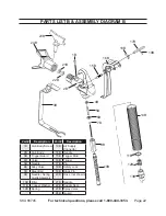
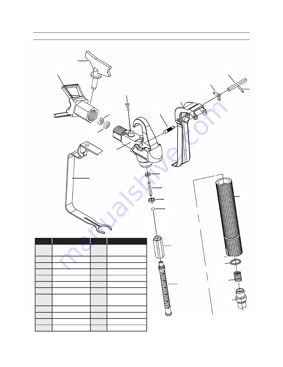
parts list B & assemBly diagram B

part #

description

part #

description

1B

Gun Body Screw

13B Air Supply  

Connector

2B

Gun Body

14B Handle

3B

Trigger Guard

15B Trigger Stud

4B

Valve

16B Trigger

5B

Needle

17B Pin

6B

Alloy Valve

18B Safety Lock

7B

Steel Ball

19B Block Pin

9B

Needle / Spring 

Guide Assembly

20B Hose (not shown)

10B Filter

21B Saddle

11B Copper Washer

22B Saddle Seal

12B Spring

23B Spray Valve
24B Guard

23B

21B

22B

1B

2B

3B

4B

5B

6B

7B

9B

10B

15B

16B

17B

18B

19B

24B

11B

12B

13B

14B

Summary of Contents for 66745

Page 1: ... rights reserved No portion of this manual or any artwork contained herein may be reproduced in any shape or form without the express written consent of Harbor Freight Tools Diagrams within this manual may not be drawn proportionally Due to continuing improvements actual product may differ slightly from the product described herein Tools required for assembly and service may not be included For te...

Page 2: ...ORDS 9 SYMBOLOGY 10 SPECIFICATIONS 11 UNPACKING 11 ASSEMBLY INSTRUCTIONS 11 PRODUCT FEATURES 12 OPERATING INSTRUCTIONS 13 PAINTING TIPS 14 MAINTENANCE AND SERVICING 15 TROUBLESHOOTING 19 PARTS LIST A 20 ASSEMBLY DIAGRAM A 21 PARTS LIST B ASSEMBLY DIAGRAM B 22 IMPORTANT WARRANTY INFORMATION 23 PLEASE READ THE FOLLOWING CAREFULLY 23 ...

Page 3: ...t symbol indicates a hazardous situation which if not avoided could result in minor or moderate injury NOTICE is used to address practices not related to personal injury CAUTION without the safety alert symbol is used to address practices not related to personal injury General Safety Warnings WARNING Read all safety warnings and instructions Failure to follow the warnings and instructions may resu...

Page 4: ...rsonal protective equip b ment Always wear eye protection Safety equipment such as dust mask non skid safety shoes hard hat or hearing protection used for appropriate conditions will reduce personal injuries Prevent unintentional starting c Ensure the switch is in the off po sition before connecting to power source and or battery pack pick ing up or carrying the tool Carrying power tools with your...

Page 5: ...aking into account the working conditions and the work to be performed Use of the power tool for operations different from those intended could result in a hazardous situation Service 5 Have your power tool serviced by a a qualified repair person using only identical replacement parts This will ensure that the safety of the power tool is maintained Specific Safety Warnings Maintain labels and name...

Page 6: ...lfunction or break down grounding provides a low resistance path to carry electricity away from the user Never spray materials near fire 5 flames electrical sparks or any other ignition source Never smoke when spraying or in the vicinity of spraying Never smoke unless the area has been thoroughly aired out Always provide good ventilation dur ing and after spraying to eliminate any enclosed explosi...

Page 7: ...ray area Keep the area free of paint and 12 solvent containers rags and other flammable materials Always have multiple ABC class 13 fire extinguishers nearby Avoid unintentional starting Pre 14 pare to begin work before turning on the tool This unit is provided with a ther 15 mally protected reset If an over load occurs the reset disconnects the Motor from the power supply When the thermally prote...

Page 8: ...r reproductive harm California Health Safety Code 25249 5 et seq WARNING Handling the Power 20 Cord 37A on this product will expose you to lead a chemical known to the State of California to cause cancer and birth defects or other reproductive harm Wash hands after handling California Health Safety Code 25249 5 et seq The warnings precautions and 21 instructions discussed in this in struction manu...

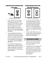
Page 9: ... and grounded in accordance with all codes and ordinances The plug and outlet should look like those in the preceding illustration See 3 Prong Plug and Outlet Double Insulated Tools Tools with Two Prong Plugs Tools marked Double Insulated do 1 not require grounding They have a special double insulation system which satisfies OSHA requirements and complies with the applicable standards of Underwrit...

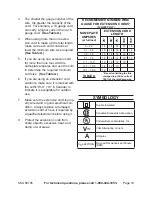
Page 10: ...dicate it is acceptable for outdoor use Make sure the extension cord is prop 7 erly wired and in good electrical con dition Always replace a damaged extension cord or have it repaired by a qualified electrician before using it Protect the extension cords from 8 sharp objects excessive heat and damp or wet areas RECOMMENDED MINIMUM WIRE GAUGE FOR EXTENSION CORDS 120 240 VOLT NAMEPLATE AMPERES at fu...

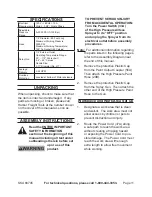
Page 11: ... subheadings therein before set up or use of this product To prevent serious injury from accidental operation Turn the Power Switch 33A of the High Pressure Airless Sprayer to its OFF position and unplug the Sprayer from its electrical outlet before assembly procedures Note For additional information regarding the parts listed in the following pages refer to the Assembly Diagram near the end of th...

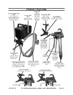
Page 12: ...se 50A Siphons paint from the paint container into the Spray Gun Return Tube 43A Paint flows from Return Tube once pressure is released in system Air Supply Connector 13B Connect end of Spray Gun Hose 20B to here Clean Mode Spray Mode Trigger 16B Press to spray or clean Safety Lock 18B Turn up to keep Trigger from being pressed Guard 24B Thread Spray Valve 23B into top of Guard Spray Valve 23B Val...

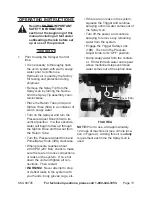
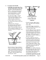
Page 13: ...hon Hose and flow out from the Return Tube Turn the Pressure Adjust Knob and Prime Spray Knob 39A clockwise When pressure reaches about 2 800 PSI 207 Bar check to make sure there are no loose connections or leaks in the system If so shut down the unit and tighten all con nections Then restart WARNING Never attempt to stop or deflect leaks in the system with your hands body gloves rags etc If there...

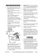
Page 14: ... recommended to test spray on scrap material Unlock the Trigger Safety Lock 18B 4 by pulling back on the tab of the Lock and turning it to either side Face the Spray Tip toward the 5 item to be painted See bottom photo on page 12 Hold the Spray Gun about 14 16 6 inches from and at a right angle to the item Move the Spray Gun first then pull the 7 Trigger to spray a test pattern Slowly increase Pum...

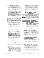
Page 15: ...oat to get the coverage you want If the surface is ruined however you will have to start over with surface preparation If the surface does not smooth out in a few seconds after applying the paint your paint mixture is probably too thick Thin your paint slightly and test on scrap material If the paint goes on very thin and threat ens to run stop spraying immediate ly Add more paint to your mixture ...

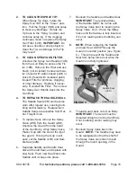
Page 16: ...ols To replace Seal remove the Spray 5 Valve 23B from the Guard 24B Unscrew the Guard from the head of the Gun Body Align Spray Valve Plastic Grip with the slot at the tip of the guard Forcing the Grip in will push out the Saddle 21B and Sad dle Seal 22B Separate Saddle and Saddle Seal 6 discard the old Seal and replace with new Seal Push new Seal back onto Saddle until it snaps into place Reinser...

Page 17: ...See Figure E above Turn the Pressure Adjust Knob to OFF and close the Prime Spray Knob 39A Unlock the Trigger and with the Spray Tip still removed and the unit in its prime clean mode Aim the Spray Gun into a paint con tainer and hold the Trigger open un til the paint flow stops and water or solvent just begins to flow Release the Trigger Aim the Spray Gun into a water or solvent container for abo...

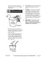
Page 18: ...Spray Gun Figure G FIGURE G After Use 6 clean external surfaces of the Airless Sprayer with clean cloth STORING 7 Prevent Pump corrosion and damage from freezing Never leave water or water based paint in the Airless Sprayer when it is not in use in cold weather Freezing fluids can seriously damage the Sprayer Drain the system completely of liquids and store indoors at room tempera ture 8 WARNING I...

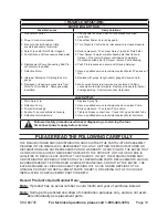
Page 19: ...tput Worn Spray Tip 1 Defective Pump 2 Prime Valve leaking 3 Suction Tube connections not secure 4 Defective Motor Armature 5 Replace Spray Tip 1 Have a qualified service technician repair or replace Pump 2 Relieve pressure Then repair Prime Valve 3 Tighten all loose connections Check O Ring on Suction Tube 4 Have a qualified service technician replace Motor Armature 5 Follow all safety precaution...

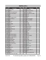
Page 20: ...Connector 1 14A Piston Wrap A 1 49A Retaining Clip 1 15A O Ring 1 50A Siphon Hose 1 16A Piston Wrap B 1 51A Inlet Screen 1 17A O Ring 1 52A Washer 1 18A O Ring 1 53A Ball 1 19A Pin 2 54A Washer 1 20A Small Gear Wrap A 1 55A Spring 1 21A Small Gear Wrap B 1 56A Output Coupler 1 22A Large Gear Wrap B 1 57A O Ring 1 23A Crankshaft 1 58A Cover 1 24A 2nd Stage Gear 1 59A O Ring 2 25A Motor Holder 1 60A...

Page 21: ...A 6A 7A 8A 9A 5A 11A 11A 12A 22A 23A 24A 20A 21A 25A 26A 27A 28A 29A 30A 31A 32A 33A 34A 35A 36A 37A 38A 39A 40A 58A 41A 42A 43A 44A 45A 46A 47A 48A 49A 50A 51A 13A 14A 15A 16A 17A 18A 52A 53A 54A 55A 56A 57A 59A 60A 61A 67A 62A 63A 66A 69A 65A 68A 69A NOTE USE A SUFFIX WHEN ORDERING PARTS ON THIS PAGE ...

Page 22: ... 2B Gun Body 14B Handle 3B Trigger Guard 15B Trigger Stud 4B Valve 16B Trigger 5B Needle 17B Pin 6B Alloy Valve 18B Safety Lock 7B Steel Ball 19B Block Pin 9B Needle Spring Guide Assembly 20B Hose not shown 10B Filter 21B Saddle 11B Copper Washer 22B Saddle Seal 12B Spring 23B Spray Valve 24B Guard 23B 21B 22B 1B 2B 3B 4B 5B 6B 7B 9B 10B 15B 16B 17B 18B 19B 24B 11B 12B 13B 14B ...
Page 23: ...cidental or consequential damages so the above limitation of exclusion may not apply to you This warranty is express ly in lieu of all other warranties express or implied including the warranties of merchantability and fitness To take advantage of this warranty the product or part must be returned to us with transportation charges prepaid Proof of purchase date and an explanation of the com plaint...

Reviews: