background image

Page 14

SKU 41213

For technical questions, please call 1-800-444-3353.


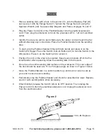
   15 to 25 Degrees

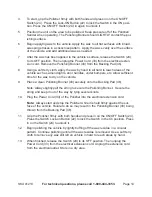
To start, grip the Polisher firmly with both hands and press in on the ON/OFF 

Switch (24).  Press the Lock-ON Button (22) to lock the Switch in the ON posi-

tion. Press the ON/OFF Switch (24) in again to unlock it.
Position the unit on the area to be polished. Keep pressure off of the Polisher/

Sander when operating. The Polishing Bonnet should LIGHTLY contact the pol-

ishing surface.

Begin applying wax to the vehicle. Apply the wax to all flat surfaces with broad, 

sweeping strokes in a crisscross pattern.  Apply the wax evenly over the surface 

of the vehicle, and add additional wax as needed.
After the wax has been applied to the vehicle’s surface, release the Switch (24) 

to its OFF position. Then unplug the Power Cord (33) from the electrical exten-

sion cord. Remove the Polishing Bonnet (4) from the Backing Pad (4). 
Using a soft terry cloth, apply the wax by hand to all hard to reach areas of the 

vehicle such as around lights, door handles, under bumpers, etc. Allow sufficient 

time for the wax to dry on the vehicle.
Place a clean Polishing Bonnet (4) securely onto the Backing Pad (4). 
Note: Always tightly pull the string to secure the Polishing Bonnet.  Secure the 

string and keep it out of the way by tying several knots.
Plug the Power Cord (33) of the Polisher into the electrical extension cord.

note:

  Always start and stop the Polisher while it is held firmly against the sur

-

face of the vehicle. Failure to do so may result in the Polishing Bonnet (4) being 

thrown from the Backing Pad (4).

Grip the Polisher firmly with both hands and press in on the ON/OFF Switch (24). 

Press the Switch Lock-on Button (22) to lock the Switch in the On position. Press 

in on the Switch (24) to unlock it.

Begin polishing the vehicle by lightly buffing off the wax residue in a circular 

pattern. Continue polishing until all the wax residue is removed. Use a soft terry 

cloth to remove any wax still left on vehicle in hard to reach areas by hand.

When finished, release the Switch (24) to its OFF position. Then unplug the 

Power Cord (33) from the electrical extension cord. Unplug the extension cord 

from the electrical outlet. Store in a dry area.
 

4.

.

.

7.

.

9.

10.

11.

12.

13.

Summary of Contents for 41213

Page 1: ...91 Mission Oaks Blvd Camarillo CA 93011 Visit our website at http www harborfreight com Read this material before using this product Failure to do so can result in serious injury Save this manual Copy...

Page 2: ...the safety alert symbol It is used to alert you to potential personal injury hazards Obey all safety messages that follow this symbol to avoid possible injury or death DANGER indicates a hazardous sit...

Page 3: ...hock Avoid body contact with grounded surfaces such as pipes radiators ranges and refrigerators There is an increased risk of electric shock if your body is grounded Do not expose power tools to rain...

Page 4: ...ob better and safer at the rate for which it was designed Do not use the power tool if the switch does not turn it on and off Any power tool that cannot be controlled with the switch is dangerous and...

Page 5: ...al symptoms related to vibration such as tingling numbness and white or blue fingers seek medical advice as soon as possible Do not smoke during use Nicotine reduces the blood supply to the hands and...

Page 6: ...ing pads with a hook and loop back that at taches securely to the Backing Pad Connect to a GFCI Always connect the Line Cord to a Ground Fault Circuit Interrupter GFCI protected electrical outlet Acce...

Page 7: ...rilling and other construction activities contains chemicals known to the State of Califor nia to cause cancer birth defects or other reproductive harm Some ex amples of these chemicals are Lead from...

Page 8: ...ding provides a low resistance path to carry electricity away from the user reducing the risk of electric shock See 3 Prong Plug and Outlet The grounding prong in the plug is connected through the gre...

Page 9: ...uge number of the wire the greater the capacity of the cord For example a 14 gauge cord can carry a higher current than a 16 gauge cord See Table A When using more than one extension cord to make up t...

Page 10: ...150 Feet 0 2 0 18 18 18 18 16 2 1 3 4 18 18 18 16 14 3 5 5 0 18 18 16 14 12 5 1 7 0 18 16 14 12 12 7 1 12 0 18 14 12 10 12 1 16 0 14 12 10 16 1 20 0 12 10 TABLE A Based on limiting the line voltage d...

Page 11: ...herein before set up or use of this product Risk of accidental starting resulting in serious personal injury Turn the Power Switch of the tool to its OFF position and unplug the tool from its electric...

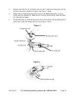
Page 12: ...ishing Bonnet 48 on top of the Backing Pad 46 Tie it se curely using the drawstring Make sure to tuck any excess string inside the Bon net See Figure 2 below 3 4 Backing Pad 46 Flange Nut 47 Stop Pin...

Page 13: ...ndamaged one Harbor Freight Tools cannot be held responsible for damage caused by using a damaged accessory on this tool Note Avoid using too much wax For additional applications of wax to the Polish...

Page 14: ...les under bumpers etc Allow sufficient time for the wax to dry on the vehicle Place a clean Polishing Bonnet 48 securely onto the Backing Pad 46 Note Always tightly pull the string to secure the Polis...

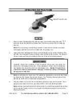
Page 15: ...the Switch 24 trigger Press the Switch Lock on Button 22 to lock the Switch in the ON position Press in on the Switch 24 to unlock it Position the unit on the area to be sanded Keep heavy pressure off...

Page 16: ...ect the general condition of the tool Check for loose screws misalignment or binding of moving parts cracked or broken parts dam aged electrical wiring and any other condition that may affect its safe...

Page 17: ...1 34 Side Handle 1 10 Armature 1 35 Axle Check Ring 1 11 Bearing 1 36 Bearing 1 12 Bearing Screw 1 37 Axle Check Ring 1 13 Fan Guide 1 38 Gear 1 14 Screw 1 39 Screw 1 15 Stator 1 40 Bearing Cover 1 16...

Page 18: ...18 SKU 41213 For technical questions please call 1 800 444 3353 ASSEMBLY DIAGRAM Note Some parts are listed and shown for illustration purposes only and are not avail able individually as replacement...

Page 19: ...f this warranty the product or part must be returned to us with transportation charges prepaid Proof of purchase date and an explanation of the com plaint must accompany the merchandise If our inspect...

Reviews: