


ENGINE-ELECTRICAL 6Y-23
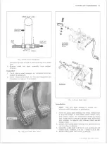
Fig. 14i — L—6 Spark Plug Wire Installation
gages will not give a correct measurement if the elec
trodes are worn. Adjust gap by bending the side elec
trodes only; bending the center electrode will crack the
insulator. Adjust gaps to specification. Setting spark plug
gap to other than specification to effect changes in engine
performance is not recommeded.
CAUTION:
Before adjusting gap, file center elec
trode flat. In adjusting the spark plug gap, never
bend the center electrode which extends through
the porcelain center. Always make adjustment by
bending the ground or side electrode.
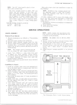
Installation of Spark Plugs
When installing spark plugs, make sure that all surfaces
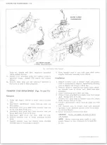
Fig. 15i —V —8 Spark Plug Wire Installation
on plugs and in cylinder heads are clean. When installing
the 5/8” hex tapered seat spark plugs, tighten to 15 lb. ft.,
using a 5/8,; deep socket, an extension and a torque
wrench.
CAUTION:
If tapered seat spark plugs are over-
tightened, they will be more difficult to remove
at the next tune-up.
Installation of Spark Plug Wires
No. 1 spark plug wire is installed in the first distributor
cap tower after the adjusting window, moving in the direc
tion of rotation (V-8), or in the foremost tower (L-6). The
other wires are then installed in a clockwise direction
according to the firing order (figs. 14i and 15i).
STARTING SYSTEM
INDEX
Page
Page
Starting M o to r and Solenoid C h e c k s ........................................6Y-25
C om ponent P a r t R e p lac e m e n t .................................. * ..................6Y-25
GENERAL DESCRIPTION
The function of the starting system, composed of the
starting motor, solenoid and battery, is to crank the
engine. The battery supplies the electrical energy, the
solenoid completes the circuit to the starting motor, and
the motor then does the actual work of cranking the engine.
The starting motor (fig. Is) consists primarily of the
drive mechanism, frame, armature, brushes, and field
windings. The starting motor is a 12-volt extruded frame
type, having four pole shoes and four fields, connected
with the armature. The aluminum drive end housing is
extended to enclose the entire shift lever and plunger
mechanism, protecting them from dirt, splash, and icing.
The flange mounted solenoid switch operates the overrun
ning clutch drive by means of a linkage to the shift lever.
10-30 CHEVROLET TRUCK SERVICE MANUAL
Summary of Contents for 10 1971 Series
Page 1: ......
Page 96: ......
Page 100: ...10 30 CHEVROLET TRUCK SERVICE MANUAL Fig 4 10 30 Series Truck Frame FRAME 2 4 ...
Page 120: ......
Page 203: ...ENGINE 6 25 Fig 22L Engine Mounts 10 30 CHEVROLET TRUCK SERVICE MANUAL ...
Page 215: ...ENGINE 6 37 REAR M O U NT Fig 21V Engine Mounts 10 30 CHEVROLET TRUCK SERVICE MANUAL ...
Page 218: ......
Page 249: ......
Page 324: ......
Page 340: ......
Page 365: ...10 30 CHEVROLET TRUCK SERVICE MANUAL Fig 43 Power Steering Pump M ounting STEERING 9 25 ...
Page 368: ......
Page 386: ......
Page 390: ...ELECTRICAL BODY AND CHASSIS 12 4 10 30 CHEVROLET TRUCK SERVICE MANUAL ...
Page 391: ......
Page 428: ......
Page 432: ......
Page 449: ...SPECIFICATIONS 9 10 30 CHEVROLET TRUCK SERVICE MANUAL ...
Page 463: ......
Page 464: ......
Page 465: ......
Page 466: ......


