


ENGINE-ELECTRICAL 6Y-24
M AIN TENANCE A N D ADJUSTMENTS
LUBRICATION
The gasoline engine type starting motors have graphite
and oil impregnated bronze bearings and therefore re
quire no periodic lubrication between major overhauls.
RESISTANCE CHECKS
Although the starting motor cannot be checked against
specifications on the car, a check can be made for exces
sive resistance in the starting circuit. Place a voltmeter
across points in the cranking circuit as outlined below and
observe the reading with the starting switch closed and
the motor cranking (distributor primary lead grounded to
prevent engine firing).
1. From battery positive post to solenoid battery ter
minal.
2. From battery negative post to starting motor housing.
3. From solenoid battery terminal to solenoid motor
terminal.
If voltage drop is any of above, check exceeds 0.2 volts,
excessive resistance is indicated in that portion of start
ing circuit and the cause of the excessive resistance could
be located and corrected in order to obtain maximum
efficiency in the circuit.
CAUTION:
Do not operate the starting motor
continuously for more than 30 seconds to avoid
overheating.
When the solenoid fails to pull in, the trouble may be
due to excessive voltage drop in the solenoid control cir
cuit. To check for this condition, close the starting switch
and measure the voltage drop between the BATTERY ter
minal of the solenoid and the SWITCH (S) terminal of the
solenoid.
1. If this voltage drop exceeds 3.5 volts, excessive re
sistance in the solenoid control circuit is indicated
and should be corrected.
2. If the voltage drop does not exceed 3.5 volts and
the solenoid does not pull in, measure the voltage
available at the SWITCH terminal of the solenoid.
3. If the solenoid does not feel warm, it should pull in
whenever the voltage available at the SWITCH ter
minal is 7.7 volts or more. When the solenoid feels
warm, it will require a somewhat higher voltage to
pull in.
STARTING M OTOR A N D SOLENOID CHECK
The following checks may be made if the specific gravity
of the battery is 1.215 or higher.
1. If the solenoid does not pull in, measure the voltage
between the switch (S) terminal of the solenoid and
ground with the starting switch closed.
CAUTION:
If the solenoid feels warm, allow to
cool before checking.
If the voltage is less than 7.7 volts, check for ex
cessive resistance in the solenoid control circuit. If
the voltage exceeds 7.7 volts, remove the starting
motor and check (1) solenoid current draw, (2) start
ing motor pinion clearance, and (3) freedom of shift
lever linkage.
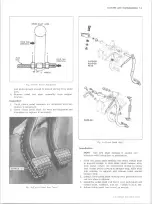
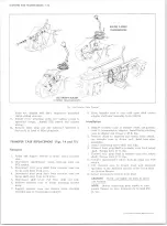
SOLENOID
PLUNGER
GROMMET
BUSHING
BUSHING
CONTACT
FINGER
BRUSH
TURN SPRING
SHIFT
LEVER
SPIRAL
SPLINES
INSULATED BRUSH HOLDER
\
FIELD COIL
\
BRUSH SPRING
ARMATURE
GROUNDED BRUSH HOLDER
PIN IO N
STOP
O VERRUNN IN G
ASSIST
CLUTCH
SPRING
Fig. ls-S ta rtin g M otor Cross Section - Light Duty
10-30 CHEVROLET TRUCK SERVICE MANUAL
Summary of Contents for 10 1971 Series
Page 1: ......
Page 96: ......
Page 100: ...10 30 CHEVROLET TRUCK SERVICE MANUAL Fig 4 10 30 Series Truck Frame FRAME 2 4 ...
Page 120: ......
Page 203: ...ENGINE 6 25 Fig 22L Engine Mounts 10 30 CHEVROLET TRUCK SERVICE MANUAL ...
Page 215: ...ENGINE 6 37 REAR M O U NT Fig 21V Engine Mounts 10 30 CHEVROLET TRUCK SERVICE MANUAL ...
Page 218: ......
Page 249: ......
Page 324: ......
Page 340: ......
Page 365: ...10 30 CHEVROLET TRUCK SERVICE MANUAL Fig 43 Power Steering Pump M ounting STEERING 9 25 ...
Page 368: ......
Page 386: ......
Page 390: ...ELECTRICAL BODY AND CHASSIS 12 4 10 30 CHEVROLET TRUCK SERVICE MANUAL ...
Page 391: ......
Page 428: ......
Page 432: ......
Page 449: ...SPECIFICATIONS 9 10 30 CHEVROLET TRUCK SERVICE MANUAL ...
Page 463: ......
Page 464: ......
Page 465: ......
Page 466: ......


