


SECTION 4
REAR SUSPENSION AND DRIVE LINE
CONTENTS OF THIS SECTION
Page
Page
Rear Suspension .........
Drive Line ................
Rear Axle (Chevrolet)
4-1
Propeller Shafts, Universal Joints and
4-6
Bearing S u p p o r t.................. . . . . ......................................................
4-22
4-6
REAR SUSPENSION
INDEX
Page
Page
Components Parts Replacement .................................. .......................
4-1
Leaf Springs....................................... .......................................................
4-5
Shock Absorber Replacem ent.................................. .......................
4-1
Bushing Replacement ..................... .......................................................
4-6
Tie Rod ....................................................................... .......................
4-1
Spring Replacement.........................
Stabilizer Shaft.......................................................................................
4-2
Spring Leaf Replacement .............. .......................................................
4-6
Control Arm
.............................................................. .......................
4-3
Shackle Replacement .....................
4-6
Coil Spring and Auxiliary Leaf S p rin g ......................... .......................
4-4
Specifications ..................................
COMPONENT PARTS REPLACEMENT
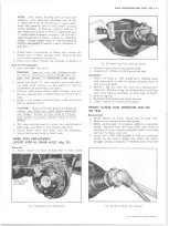
SHOCK ABSORBER (Fig. 1 and 2)
Replacement
1. Raise vehicle on hoist.
2. If equipped with airlift shock absorber bleed air out
of lines. Disconnect line from shock absorber.
3. Remove shock absorber pivot bolt nuts and washers;
pull bolts and remove from vehicle.
4. Position eye at large end of shock absorber in frame
bracket or crossmember install bolt, washer and
nut. If equipped with airlift shocks, install shock
absorber with the air fitting pointed rearward.
5. Align opposite end of shock absorber with anchor
bracket at axle, install bolt, washer and nut.
6. Tighten nuts to specifications.
7. If equipped with airlift shock absorbers, inflate to
10-15 lbs. minimum air pressure.
8. Lower vehicle and remove from hoist.
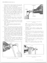
TIE ROD (SERIES C-P10 and C20) (Fig. 3)
Removal
1. Raise vehicle on hoist.
Fig. 1— Shock Absorber Installation— C P20, K 1 0 -2 0 M odels
Fig. 2 — Shock Absorber Installation— C P I 0 M odels
10-30 CHEVROLET TRUCK SERVICE MANUAL
Summary of Contents for 10 1971 Series
Page 1: ......
Page 96: ......
Page 100: ...10 30 CHEVROLET TRUCK SERVICE MANUAL Fig 4 10 30 Series Truck Frame FRAME 2 4 ...
Page 120: ......
Page 203: ...ENGINE 6 25 Fig 22L Engine Mounts 10 30 CHEVROLET TRUCK SERVICE MANUAL ...
Page 215: ...ENGINE 6 37 REAR M O U NT Fig 21V Engine Mounts 10 30 CHEVROLET TRUCK SERVICE MANUAL ...
Page 218: ......
Page 249: ......
Page 324: ......
Page 340: ......
Page 365: ...10 30 CHEVROLET TRUCK SERVICE MANUAL Fig 43 Power Steering Pump M ounting STEERING 9 25 ...
Page 368: ......
Page 386: ......
Page 390: ...ELECTRICAL BODY AND CHASSIS 12 4 10 30 CHEVROLET TRUCK SERVICE MANUAL ...
Page 391: ......
Page 428: ......
Page 432: ......
Page 449: ...SPECIFICATIONS 9 10 30 CHEVROLET TRUCK SERVICE MANUAL ...
Page 463: ......
Page 464: ......
Page 465: ......
Page 466: ......


