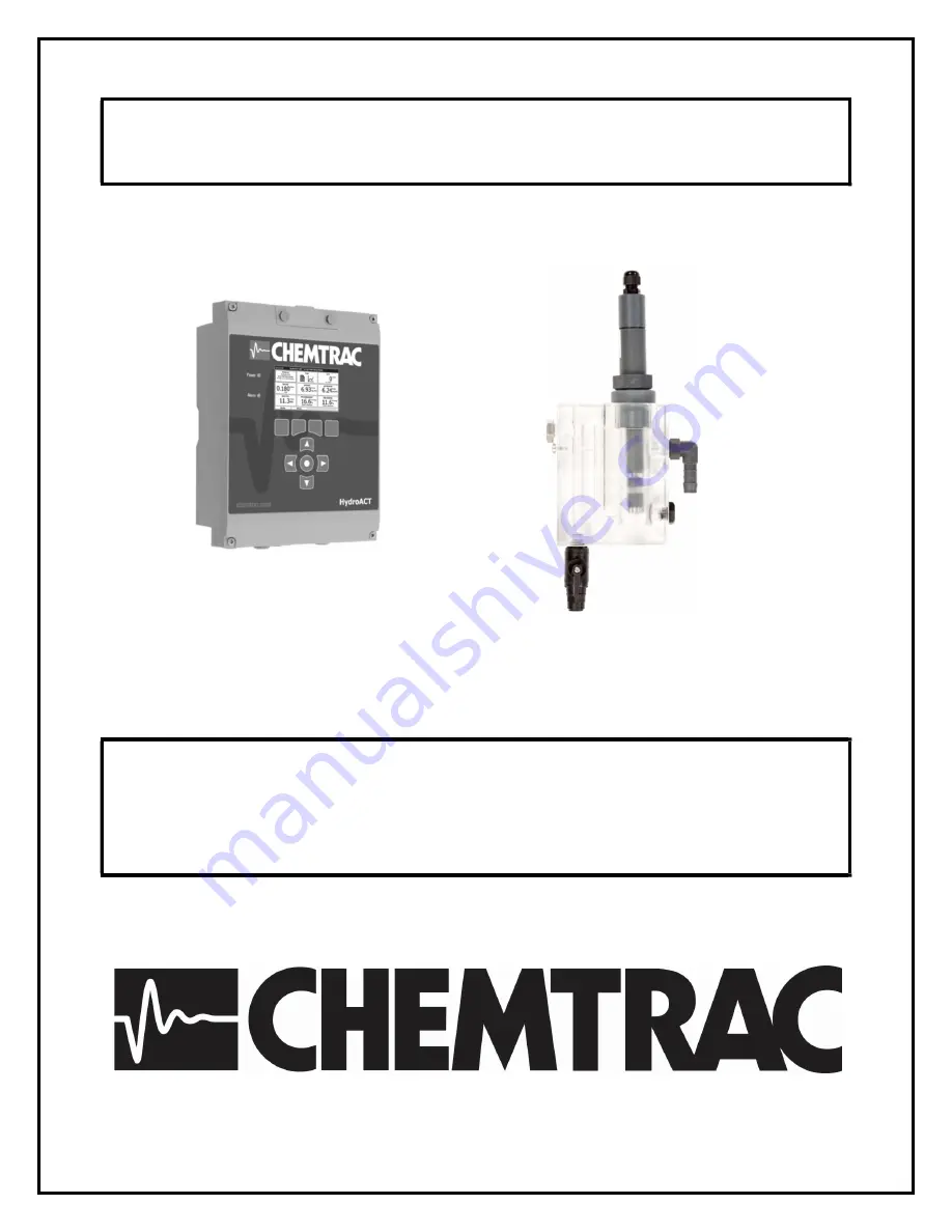
Quick Start Guide
HydroACT Analyzer with
Free or Total Chlorine Sensor
Version 03/10/2020
Page 1: ...Quick Start Guide HydroACT Analyzer with Free or Total Chlorine Sensor Version 03 10 2020...
Page 2: ...2...
Page 3: ...This Quick Start Guide is a supplement to the User Manual and is intended to give an overview of the product accessories and set up prior to installation The user is advised to review the full produc...
Page 4: ...easurement accuracy With the vented design it is very important to not have any backpressure on the drain line as this would limit how much flow would be able to pass through the probe chamber before...
Page 5: ...n Line Connections Flow Cell with Single Probe Chamber HydroACT Analyzer A mounting template and screws are provided with analyzer Mounting Holes 1 7 6 in 194 mm 2 9 4 in 238 mm Dimensions 1 4 1 in 10...
Page 6: ...ce is applied In lifting the cover position it to insert the display posts into the post holes as indicated allowing the cover to temporarily rest in the raised position After completing wiring inside...
Page 7: ...shows where the connections are located for the 4 20 mA and 4 20 mA on output card See next page for the analog output setup and scaling instructions Relays and Digital Inputs Optional Relays and Digi...
Page 8: ...r or analog output was supplied the user should verify the settings before wiring User can change the mapping and output scaling if desired Note Press the Next button to navigate through the 3 setup s...
Page 9: ...with a Total Chlorine probe should be labeled Total or have the part number ECP1 4 Damage can occur to the probe if the incorrect electrolyte is used Position the probe vertically so that the electro...
Page 10: ...is typically adequate to keep air bubbles from forming on the membrane Sample Flow Considerations For proper operation a minimum of 250 ml min sample flow is required Large changes in flow e g from 25...
Page 11: ...hich is accessed by pressing Menu and then selecting the Free or Total chlorine tile 4 Press the keypad button directly below the Calibrate icon on the display Then select Calibrate Span Follow the us...
Page 12: ...e tip where the white dot is located See page 10 of this document for instructions on how to position probe and adjust flow to deal with air bubbles 5 Ensure the cable is screwed all the way onto the...