background image

48

Intelect® Mobile Ultrasound

SYSTEM UTILITIES (CONTINUED)


2 . 

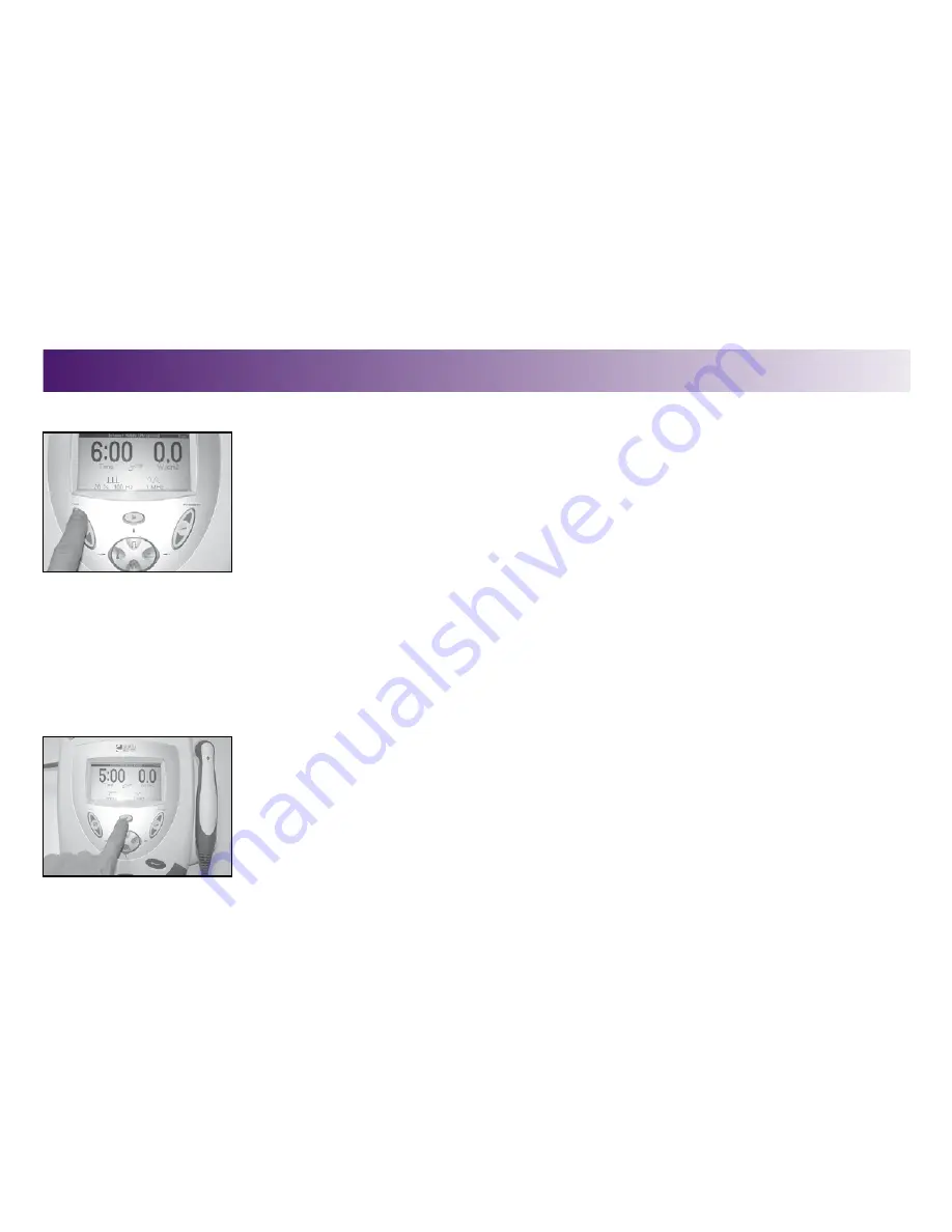
To make INTENSITY and treatment TIME changes, touch the respective buttons and use  


the up or down arrows to advance to the desired settings .

Changing Power-Up Presets

The following power up presets can be changed and stored as new presets: 
 

• Frequency 


• Duty Cycle 


• Treatment Time 


• Intensity 


• Pulse Frequency 


To change the power up presets, do the following:


1 . 

Make the desired changes . 


2 . 

Press the Clinical Resources button . 


The Clinical Resources menu displays . 

OPERATION

Summary of Contents for Intelect Mobile Ultrasound

Page 1: ...User Manual Ref 2776 Intelect Mobile Ultrasound DJO is an ISO 13485 Certified Company ...

Page 2: ...cifications 18 Unit Specifications 18 Ultrasound Technical Specifications 19 Description Of Device Markings 21 SETUP 22 Mounting the Unit on the Wall 22 Installing the Battery Pack 25 Charging and Using the Battery Pack 27 Charging the Battery Pack 27 Using the Battery Pack 27 Operation 28 Using Clinical Indications 28 Creating a User Protocol 32 Restoring Factory Settings 34 Restoring Factory Pro...

Page 3: ...ture 53 Viewing Unit Version Information 54 ACCESSORIES 56 Standard Accessories 56 Optional Accessories 56 Troubleshooting 57 Error Messages 57 Troubleshooting the Display 57 Troubleshooting Error Messages 57 Maintenance 58 Maintaining the Intelect Mobile Ultrasound 58 Cleaning 58 Service 58 Warranty 59 ...

Page 4: ... application of therapeutic ultrasound Product Description The Intelect Mobile Ultrasound designed and manufactured by DJO LLC offers a new dimension in portable ultrasound therapy made possible by advanced software design and digital signal processing The result is a unit with extraordinary versatility based on simplicity of operation The Intelect Mobile Ultrasound allows you to select a frequenc...

Page 5: ...rs a 20 degree contour in the applicator hand grip This ergonomic extra will help deliver uniform ultrasound with greater clinician comfort Head Warming A feature traditionally available in more expensive brands of ultrasound This will help curb the anxiety of patients during the first moments of treatment Clear LCD display Guide the operator through the setup process providing continuous feedback...

Page 6: ...for use only with Chattanooga Intelect Mobile Stim Combo Laser and Ultrasound systems This unit should be operated in temperatures between 15 to 40 C 59 to 85 F and transported and stored in temperatures between 7 to 43 C 20 to 110 F with relative humidity ranging from 30 60 Where the integrity of the external protective earth conductor arrangement is in doubt equipment shall be operated from its ...

Page 7: ...t the interference using one or more of the following Reorient or relocate the receiving device increase the separation between the equipment connect the equipment to an outlet on a different circuit from that to which the other device s are connected and or consult the factory field service technician for help Use of parts or materials other than DJO s can degrade minimum safety Always keep the s...

Page 8: ...Intelect Mobile Ultrasound This equipment is not designed to prevent the ingress of water or liquids Ingress of water or liquids could cause malfunction of internal components of the system and therefore create a risk of injury to the patient Use of controls or adjustments or performance of procedures other than those specified herein may result in hazardous conditions causing damage to the batter...

Page 9: ... of a ruptured or leaking battery can cause respiratory irritation Hypersensitivity to nickel can cause allergic pulmonary asthma Contents of cell coming in contact with skin can cause skin irritation and or chemical burns Never under any circumstances open the battery pack housing or cells Should an individual battery from a battery pack become disassembled spontaneous combustion of the negative ...

Page 10: ...ment time This mode imparts the most energy to the tissues and is used when a maximal effect is desired See Duty Cycle Coupling Media An agent used to insure that the ultrasound is transmitted from the sound head to the tissue to be treated Gels or lotions labeled for therapeutic ultrasound use are recommended Utilizing ultrasound waves through muscle nerve and connective tissue has been well docu...

Page 11: ...by vibrating 1 000 000 1 MHz or 3 000 000 3 MHz times per second This type of crystal is both durable and efficient in its functions Power A measure of the intensity of the ultrasound delivered to the patient Unit of measure is watts W Pulse Duration Refers to the amount of time the ultrasound is being delivered in the pulsed mode For example in the 20 duty cycle mode the ultrasound is delivered f...

Page 12: ...the ultrasonic energy having a cross sectional area of 8 5 cm2 for the 10 cm2 sound head when measured at a point 5 mm from the transducer face The energy distribution within the radiated field is 3 0 W cm2 maximum and it takes a generally conic shape having decreasing intensity at progressively increasing distance from the face of the transducer This field distribution applies for the radiation e...

Page 13: ...area This device should not be used on patients suspected of carrying serious infectious disease and or disease where it is advisable for general medical purposes to suppress heat or fevers This device should not be used over or near bone growth centers until bone growth is complete This device should not be used over the thoracic area if the patient is using a cardiac pacemaker This device should...

Page 14: ...reme caution with these patients e g diabetes neural damage etc Bony prominences are especially vulnerable they reflect sound waves and increase intensity to the periosteum ABOUT ULTRASOUND THERAPY DANGER Patients with an implanted neurostimulation device must not be treated with or be in close proximity to any shortwave diathermy microwave diathermy therapeutic ultrasound diathermy or laser diath...

Page 15: ...st or if the sound head does not maintain good contact with the skin the therapeutic effect of the sound waves will be reduced and the sound head may overheat Patient Susceptibility Some patients are more sensitive to ultrasound output and may experience a reaction similar to a heat rash Be sure to inspect the treatment area during and following treatment and discontinue if an adverse reaction doe...

Page 16: ... Pause Stop Start Intensity Frequency Down Arrow Duty Cycle Pulse Frequency Up Arrow Clinical Resources Head Warming Back Time Intensity Display Enter Sound Head Power On Off LCD LED Indicator Output Power LCD Intensity Contrast Dial Applicator ...

Page 17: ...ectricity to the unit LCD The LCD Liquid Crystal Display allows the user to view and monitor the information displayed during ultrasound therapy The following information is displayed on the LCD Frequency Duty Cycle Power Treatment Time Clinical Indications Clinical Resources Select this button to access the following functions Clinical Indications Utilities Retrieve User Protocols Save User Proto...

Page 18: ...ned off Also note that when the Head Warming feature is used a small amount of ultrasound energy is being emitted Frequency Select this button to change to a frequency of 1 MHz or 3 MHz The Frequency of ultrasound determines the depth of penetration One megahertz penetrates approximately 3 to 5 centimeters and 3 megahertz penetrates less than or equal to 2 centimeters Both 1 and 3 MHz frequencies ...

Page 19: ...in all duty cycles except Continuous The available pulse frequencies are 16 48 and 100 Hz Battery Indicator When displayed on the LCD this symbol indicates the battery pack option is present on the Intelect Mobile Ultrasound This symbol also displays the charge status of the battery LCD Intensity Contrast Dial If the intensity of the LCD display diminishes turn the dial until the display contrast ...

Page 20: ...s been started but the sound head has become uncoupled with the patient s skin This symbol indicates that therapy is in progress the sound head is adequately coupled with the patient s skin output is being distributed to the patient and the applicator is functioning normally This symbol indicates that the Pause button has been pressed and no output is being emitted from the applicator This symbol ...

Page 21: ...z 75 W Max Electrical Class CLASS I Degree of Protection Against Electrical Shock TYPE B Degree of Protection Against Ingress of Water IPXO Battery Type Nickel Metal Hydride NiMH 1 2V x 20 size AA UNIT SPECIFICATIONS DIMENSIONS Height with base 16 3 cm 6 4 in Width with applicator 28 8 cm 11 3 in Width without applicator 23 9 cm 9 4 in Depth front to rear 32 8 cm 12 9 in ...

Page 22: ...bove 10 of maximum Amplitude 0 to 2 5 w cm2 in Continuous mode 0 3 w cm2 in pulsed modes Temporal Peak to Average Ratios 2 1 20 for 50 Duty Cycle 5 1 20 for 20 Duty Cycle 9 1 20 for 10 Duty Cycle Ultrasound Technical specifications Maximum Treatment Time 30 Minutes Output Pulsed 1 MHz signal modulated 100 by the 100 Hz rectangular wave with the selected Duty Cycle Continuous 1 MHz nominal signal t...

Page 23: ...t Ingress of Water IPX7 Coupling 2 8 watts 10 cm2 Sound Head Frequency 1 MHz all 5 Power 1 MHz 0 watt to 20 watts 3 MHz 0 watt to 10 watts Effective Radiating Area 6 8 cm2 10 cm2 Maximum beam non uniformity ratio 5 0 1 Beam Type Collimating Degree of Protection Against Ingress of Water IPX7 Coupling 1 MHz 2 18 watts 3 MHz 2 8 watts 2 cm2 Sound Head Frequency 1 MHz all 5 Power 0 watt to 4 watts Eff...

Page 24: ...ainst Electrical Shock Type B EU Directive on Waste Electrical and Electronic Equipment WEEE ensures that product is appropriately disposed of or recycled at the end of its life The markings on the unit are assurance of its conformity to the highest applicable standards of medical equipment safety and electromagnetic compatibility One or more of the following markings may appear on the device SPEC...

Page 25: ...perated while the unit is resting on a flat surface or mounted on a wall To mount the unit on a wall do the following 1 Remove the mounting bracket from the back of the unit 2 Using the bracket as a guide mark the 4 wall holes with a pencil or pen Mounting the unit on the wall ...

Page 26: ... 4 Press 4 appropriately sized sheetrock anchors into the wall so that the sheetrock anchor is flush with the wall 5 Screw four 8 flathead wood screws 2 54 cm or 1 inch into the wall anchors Make sure you leave 0 635 cm 1 4 of an inch between the wall and the head of the screw mounting the unit on the wall CONTINUED SETUP ...

Page 27: ...on the wall CONTINUED 6 Replace the mounting bracket on the back of the unit 7 Line up the screw heads with the holes on the mounting brackets and slide the unit down slightly until the screw heads are securely fastened to the mounting bracket SETUP ...

Page 28: ...eries The unit can operate with the rechargeable power supply for approximately five hours of continuous use To install the battery pack in the Intelect Mobile Ultrasound do the following 1 Locate the battery access door at the bottom of the unit and loosen the screw with a regular screwdriver 2 Remove the battery access door and retain this cover Installing the battery pack SETUP ...

Page 29: ... the bottom of the battery recess 4 Put the battery pack into the unit making sure to orient it as shown 5 Replace the battery access door and re tighten the screw using the screwdriver 6 Reverse the steps in this section in order to remove the battery pack INSTALLINGTHEBATTERYPACK CONTINUED SETUP ...

Page 30: ...vide 2 5 hours of treat ment depending on the power duty cycle and frequency used Note Even when the battery pack is connected the unit will default to mains power USINGTHEBATTERYPACK To save battery power the Intelect Mobile Ultrasound is equipped with a power off function This function is activated when the unit is powered on and has been left idle for approximately 5 minutes at which time the u...

Page 31: ...assessed to determine the appropriateness of the parameter setting prior to use To select an indication for a patient do the following 1 Press the Clinical Resources button The Clinical Resources menu displays 2 Using the Duty Cycle up arrow and Frequency down arrow buttons highlight Clinical Indications and press the DISPLAY enter button The Clinical Indications menu displays ...

Page 32: ...s Superficial or Deep available Chronic Tendonitis Superficial or Deep available Acute Muscle Strain Superficial or Deep available Chronic Muscle Strain Superficial or Deep available Osteoarthritis Superficial or Deep available Scar Tissue Adhesions Superficial or Deep available Raynaud s Disease Dupuytren Syndrome Reflex Sympathetic Dystrophy 4 Press the DISPLAY enter button to accept the highlig...

Page 33: ...ion you selected using the DUTY CYCLE up arrow and FREQUENCY down arrow buttons 6 Press the DISPLAY enter button to accept the highlighted selection You are returned to the main screen with the settings from the indication you selected displayed 7 Review the final protocol settings for the ultrasound treatment Make any necessary modifications or corrections OPERATION ...

Page 34: ...tensity button either the up or down arrow to adjust the output to the prescribed intensity 9 To begin therapy continue with the instructions outlined in the section entitled Preparing the Patient s Skin for Ultrasound Therapy on page 40 Then proceed to step 7 on page 43 OPERATION ...

Page 35: ...lowing 1 Make the desired parameter changes 2 Press the Clinical Resources button The Clinical Resources menu displays 3 Press the FREQUENCY down arrow or DUTY CYCLE up arrow buttons to highlight the Save Protocol option 4 Press the DISPLAY enter button to accept the Save Protocol selection The Save Protocol menu displays creating a User protocol OPERATION ...

Page 36: ...n the unit powers up 6 Press the DISPLAY enter button to accept the highlighted selection and save your custom protocol The User Protocol Confirmation window displays to indicate that the protocol is now saved as the number you specified 7 Press any button on the Operator Interface The Clinical Resources menu displays and your new user defined protocol is now saved CREATING A USER PROTOCOL CONTINU...

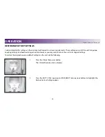
Page 37: ...e coupling settings and head warming activation However you may want to return the unit to its original settings To restore the original power up default settings on the unit do the following 1 Press the Clinical Resources button The Clinical Resources menu displays 2 Press the DUTY CYCLE up arrow or FREQUENCY down arrow buttons to highlight the Restore Factory Settings option OPERATION ...

Page 38: ...ection The Restore Factory Settings Confirmation window displays 4 Press any button to confirm that you have restored the factory settings on your unit The default power up settings are restored and you are returned to the Clinical Resources menu restoring factory settings CONTINUED OPERATION ...

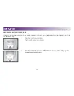
Page 39: ... defined protocols to the unit s original parameters when it was shipped to you To do this do the following 1 Press the Clinical Resources button The Clinical Resources menu displays 2 Press the DUTY CYCLE up arrow or FREQUENCY down arrow buttons to highlight the Restore Factory Protocols option OPERATION ...

Page 40: ...t the highlighted selection The Restore Factory Protocols Confirmation window displays 4 Press any button to confirm that you have restored the factory protocols on your unit The user defined protocols are erased and restored to the original parameters You are returned to the Clinical Resources menu OPERATION ...

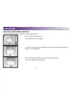
Page 41: ... Resources button The Clinical Resources menu displays 2 Use the DUTY CYCLE up arrow or FREQUENCY down arrow buttons to highlight the Retrieve User Protocol option 3 Press the Display Enter button to accept the highlighted selection A list of user defined protocols displays SELECTING A USER DEFINED protocol OPERATION ...

Page 42: ...en displays with the parameters of the protocol you selected 6 Verify the parameters of this program and use the appropriate buttons on the Operator Interface to adjust any setting if necessary For example to adjust the time press the up and down arrows on the TIME button 7 To begin therapy perform all the procedures outlined in the section entitled Preparing the Patient s Skin for Ultrasound Ther...

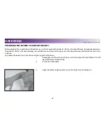
Page 43: ... more ultrasound energy to reach the targeted areas and reduce the risk of skin irritation To prepare the patient s skin for ultrasound therapy do the following 1 Thoroughly wash the skin on which you intend to place the sound head with mild soap and water or alcohol wipe 2 Dry the skin thoroughly 3 Apply the ultrasound gel generously to the target area on the patient preparing the PAtient s skin ...

Page 44: ...To apply ultrasound therapy do the following 1 Turn system power ON by pressing the Power On Off Button The unit will go through self diagnostics and the home screen displays on the LCD 2 Press the Frequency button to select 1 or 3 MHz When the button is pressed the frequency will toggle from 1 to 3 MHz and back again as long as the button is being pressed An audible tone will be heard when change...

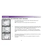
Page 45: ...n the LCD 4 Press and hold the Duty Cycle button to select a pulse frequency of 16 48 or 100 Hz You can not change pulse frequency when the Continuous duty cycle is displayed 5 Press the Time button and raise or lower treatment time using the up and down arrows 6 Press the Intensity button and raise or lower the unit s output using the up and down arrows starting stopping and interrupting therapy ...

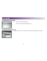
Page 46: ...g ultrasound energy and the unit returns to the default settings To resume therapy press the Start button When the PAUSE button is pressed the icon displays the timer pauses and the applicator stops emitting ultrasound energy To resume therapy press the PAUSE button again 9 The parameters of the therapy can be changed at any time during the therapy session by pressing the appropriate button 10 Aft...

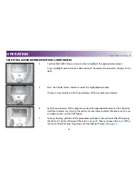
Page 47: ...e most efficient use of ultrasound therapy NOTE The green light located on the back of the applicator flashes intermittently when the sound head breaks contact with the patient Also while the sound head is in good contact with the patient the icon displays However when the sound head breaks contact with the patient s skin the icon displays assuming the Coupling Setting feature is enabled To use th...

Page 48: ...elect the manner in which you want to be notified when the sound head breaks contact with the patient s skin The following list details these options Pause timer and beep the timer stops and the unit beeps once To resume treatment simply make adequate contact with the patient s skin Pause timer no beep the timer stops but the unit does not give an audible tone To resume treatment simply make adequ...

Page 49: ...ount down and the unit beeps once Run timer no beep the timer continues to count down but the unit does not give an audible tone NOTE When the applicator becomes uncoupled during treatment it continues to distribute ultrasound energy 5 Press the Display enter button to accept the highlighted selection OPERATION ...

Page 50: ...ill display Any error message is displayed The sound head becomes uncoupled with the patient s skin and the appropriate coupling option is chosen pages 44 46 The therapy time reaches 0 00 Changing Protocol Parameters You may change any user protocol or indication parameter prior to or during therapy To change Frequency or Duty Cycle do the following 1 Press either the FREQUENCY up arrow or DUTY CY...

Page 51: ...rows to advance to the desired settings Changing Power Up Presets The following power up presets can be changed and stored as new presets Frequency Duty Cycle Treatment Time Intensity Pulse Frequency To change the power up presets do the following 1 Make the desired changes 2 Press the Clinical Resources button The Clinical Resources menu displays OPERATION ...

Page 52: ...Y enter button to accept the highlighted selection The Save Protocol window displays 4 Press the DUTY CYCLE up arrow or FREQUENCY down arrow buttons to highlight Unit Default Protocol 5 Press the DISPLAY enter button to accept the highlighted selection The User Default Protocol confirmation window displays SYSTEMUTILITIES CONTINUED OPERATION ...

Page 53: ...y key to confirm the settings You are returned to the Clinical Resources menu Brightening or Dimming the LCD To brighten or dim the LCD turn the contrast control dial until the display contrast is optimal SYSTEM UTILITIES CONTINUED OPERATION ...

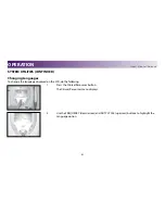
Page 54: ...hanging Languages To change the language displayed on the LCD do the following 1 Press the Clinical Resources button The Clinical Resources menu displays 2 Use the FREQUENCY down arrow and DUTY CYCLE up arrow buttons to highlight the Language option OPERATION ...

Page 55: ...enter button to accept the highlighted selection 4 Press the FREQUENCY down arrow and DUTY CYCLE up arrow buttons to highlight the appropriate language 5 Press the DISPLAY enter button to accept the highlighted selection Your unit now displays the language you selected OPERATION ...

Page 56: ...arming feature on the unit do the following 1 Press the Head Warming button The sound head will warm to slightly above body temperature A small icon of a thermometer will appear on the LCD 2 Press the Head Warming button again to disable the feature system utilities CONTINUED OPERATION ...

Page 57: ...hat the unit is using the latest software available To do this do the following 1 Press the Clinical Resources button The Clinical Resources menu displays 2 Use the FREQUENCY down arrow and DUTY CYCLE up arrow buttons to highlight the View User Info option System utilities CONTINUED OPERATION ...

Page 58: ...ile Ultrasound SYSTEM UTILITIES CONTINUED 3 Press the Display button to accept the highlighted selection The Unit Version Information window displays 4 Press any key to return to the Clinical Resources menu OPERATION ...

Page 59: ...Cord Australian 20971 Power Supply Cord Swiss 20972 Power Supply Cord UK 20973 Power Supply Cord Danish 20974 Power Supply Cord Japanese 20975 Power Supply Cord Indian 20976 Power Supply Cord Israeli 20977 Optional Accessories 1 cm2 Applicator Blue 27333 2 cm2 Applicator Blue 27334 10 cm2 Applicator Blue 27336 Battery Pack 27478 Intelect Mobile Carrying Bag 27467 Ultrasound Transmission Gel 5 lite...

Page 60: ...e contrast control dial clockwise until the display contrast is optimal Troubleshooting Error Messages The following messages are displayed in the Status Area of the LCD under the following conditions Message Displayed When Head Over Temp sound head reaches a temperature which could damage the crystal No Head Detected sound head not plugged in or faulty sound head NOTE Any error encountered by the...

Page 61: ... surface but avoid the plastic area The Intelect Mobile Ultrasound case may be cleaned by wiping with a damp cloth or mild cleaning solution Avoid abrasive cleansers NOTE The sound head must be cleaned with alcohol between each therapy session Service The Intelect Mobile Ultrasound must be recalibrated annually It is recommended that all DJO ultrasound products be returned to the factory or an aut...

Page 62: ...e in the Product caused by product misuse including but not limited to the failure to provide reasonable and necessary maintenance or any use that is inconsistent with the Product User s Manual DJO LLC is not responsible for injury or damage resulting from modifications or service performed by non authorized DJO LLC service personnel COMPANY SHALL NOT BE LIABLE IN ANY EVENT FOR INCIDENTAL OR CONSE...

Page 63: ...English DJO is an ISO 13485 Certified Company DJO France SAS Centre Européen de Fret 64990 Mouguerre France T 1 800 592 7329 USA T 1 317 406 2209 F 1 317 406 2014 chattgroup com 2011 DJO LLC All rights reserved ...

Reviews: