Charlton & Jenrick infinity 890 BF Owner'S Manual Download Page 10


10 

LT6541 (ISS 11) 

SECTION FOUR Cleaning & Laying the fuel bed (users instructions) 

CLEANING: DECORATIVE FASCIA 


Fascia assembly can be wiped with a soft, clean, dry, cloth only. 

CLEANING: BLACK PAINTED SURFACES 


These surfaces should be dusted regularly and any marks removed with a soft cloth. 


Abrasive or chemical cleaner should never be used. 

CLEANING: GLASS PANEL 

From time to time it may be necessary to clean the glass panel. 

We recommend you use a Ceramic Hob Cleaner (brands such as HOB BRITE and VITRO CLEN have been found to be 
acceptable)
 these are available from most leading Supermarkets.  

Remove the glass panel as follows: 


Undo the 3 screws that secure the heat 
deflector and remove 


Carefully lift off the outer fascia held in place by 
magnets. 


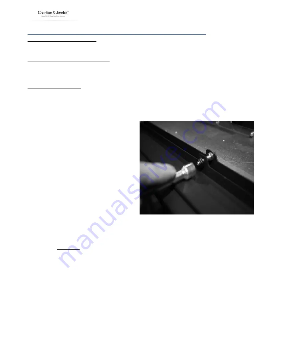
Remove the 4 nuts at the bottom securing the 
glass assembly.  


Remove  the Top 5 castle nuts on Glass Clamp, 
and slide the Glass Frame & Retaining Bracket 
completely off and disengage both parts 


Lay the glass panel down on a flat working 
surface on top of an old opened newspaper 
with the side to be cleaned uppermost. 


Follow the Instructions on the Hob Cleaner Bottle. 


On stubborn stains (where the appliance has been used for a long period without glass panel being cleaned), use a 
new Brillo Pad well wetted with the Hob cleaner applied directly to it. 


Ensure all the residues of the cleaner are removed with a damp cloth and the glass panel is completely dry before 
fitting to the appliance. 

Note: - If the loose shapes have not been placed correctly, causing the gas flame to contact the glass this may result 
in glass staining that cannot be removed by cleaning. 


Re-assemble in reverse order ensuring a tight seal against glass assembly. 


Re-fit the fascia. 


Summary of Contents for infinity 890 BF

Page 1: ...dfuturereference For use in Great Britain and Ireland Literature NO 6541 ISS 11 IMPORTANT This appliance is guaranteed for 12 months subject to conditions The 5 year extended parts warranty will only be valid if the annual service recommended in this manual has been completed and appliance has been registered online ...

Page 2: ...0 SERVICE RECORD 31 EXTENDED FIVE YEAR PARTS WARRANTY In order to validate your extended 5 years parts warranty please read the Benchmark Scheme on the opposite page and ensure your installer has filled in the appropriate checklist This in no way reduces your statutory rights Your warranty commences from the date of purchase and you must retain your receipt or invoice as proof of a purchase date T...

Page 3: ...ulations England and Wales All installations must be notified to Local Area Building Control either directly or through a Competent Persons Scheme A Building Regulations Compliance Certificate will then be issued to the customer who should on receipt write the Notification Number on the Benchmark Checklist This product should be serviced regularly to optimise its safety efficiency and performance ...

Page 4: ...tails here and keep the receipt as proof of purchase This information may be asked for when you contact the helpdesk MODEL INFINITY 890 BF Serial No This information can be found on the label attached to the packaging and on the data badge which is located on the base of the appliance behind the control cover Retailer Name Address Date Of Purchase ...

Page 5: ...rely wrapped in polythene and be clearly labelled RCF waste These materials are not classified as hazardous waste and should be disposed of at a site licensed for the disposal of industrial waste INTRODUCTION The INFINITY 890 BF is an inset room sealed decorative fuel effect gas appliance The INFINITY 890 BF is available in Natural Gas only and L P G The INFINITY 890 BF must not be installed into ...

Page 6: ...ured if placed too close to the appliance it is strongly recommended that any proposed wall covering intended for use immediately above the appliance should be tested in the hottest position immediately above first Run the fire on high over a few days All combustible material must be removed from behind the fire and fire trim The first time you light your new appliance a smell may occur due to its...

Page 7: ...ppliance will automatically go through the ignition sequence and the pilot should ignite Once the pilot is alight the appliance will automatically go to the high setting approximately 20 25sec B If the ignitor stops sparking and the pilot fails to light press the button for at least 2 seconds and release again a bleep should be heard Then repeat the lighting procedure See note on page 7 C With the...

Page 8: ...re before the appliance defaults to the pilot setting To Replace Battery In Hand Set 3 AAA type batteries Remove the cover from the rear of the handset and fit replacement battery Clock Regulation As soon as the batteries are fitted the timer digits will blink Using the arrow key increase or decrease the hour minutes and week s value By pressing the O will set and shift setting until complete Chan...

Page 9: ...d hold the Mode Key O for 5 seconds and the padlock symbol will disappear LOW BATTERY INDICATION APPLIANCE If you hear a repeated bleep sound come from the appliance this indicates the appliance battery pack is low and should be changed If this is ignored the system will go into a lock out mode which will not allow the appliance to be used until a new set of batteries are loaded NOTE The appliance...

Page 10: ...emove the 4 nuts at the bottom securing the glass assembly Remove the Top 5 castle nuts on Glass Clamp and slide the Glass Frame Retaining Bracket completely off and disengage both parts Lay the glass panel down on a flat working surface on top of an old opened newspaper with the side to be cleaned uppermost Follow the Instructions on the Hob Cleaner Bottle On stubborn stains where the appliance h...

Page 11: ...og fuel bed complete set consisting of 11 Log Shapes 9 x large shapes 2 x small shapes 1 Bag of Bark Chips Log Fuel Bed Layout The Burner End Plates should already be in position at ends of burner carrier and held in place with two self tapping screws with the chamfered ends towards the front The Air Bridge should already be fitted at the rear and held in place with two M4 x 10mm screws at either ...

Page 12: ...r the Burner Channel the Pilot cross lighting ports on the right hand side of the burner or the pilot assembly AVIOD PLACING BARK CHIPS OVER BURNER SLOT ON BURNER BAR AVOID BLOCKING PILOT ASSEMBLEY Place the first three rear straight log shapes on top of the Air Bridge as far back to the rear as possible as shown in the picture and space them evenly ...

Page 13: ...and One small shape as shown making sure they do not move the bark chips so that they cover the burner channel the smallest log shape goes in the left corner on top of the bark chips on the Burner End Plate for decorative effect Position the Smallest Log shape as shown in picture ...

Page 14: ... into the Burner Channel Place the last two large shapes and last small shape as shown making sure the last right hand shape does not cover the pilot flame The last small shape goes across the Burner and the Burner End Plate as far forward as possible to keep it out of the pilot flame as much as possible the small shape is for decorative effect ...

Page 15: ...SS 11 When positioning the Small Log Shape make sure as not to place it over the pilot assembly as this will disturb the pilot flame please see picture See Battery position the battery pack should be placed inside the Silver Heat Shield pouch ...

Page 16: ... bottom right hand side of fire box under batteries MODEL Natural Gas G20 Version L P G G31 Version Category of appliance CII CII NOX Class 5 5 Efficiency Class 1 1 Gas Category I2H I3P Gas Type G20 Natural Gas G31 L P G Gas Pressure 1 0mbar 20 mbar 37 mbar Gas Input Max 3 4 KW Gross 3 2 KW Gross Min 1 6 kW Gross 1 6 KW Gross Injectors size 230 Mark 300 Mark NOTE The efficiency of this appliance h...

Page 17: ...ce must be installed to current versions of the above standards and include any relevant amendments The Building Regulations issued by The Department of the Environment The Building Standards Scotland Consolidated Regulations issued by The Scottish Development Office IN IE Ireland The appliance must be installed by a competent person and installed in accordance with the current edition of I S 813 ...

Page 18: ...inate on a suitable outside wall The minimum flue terminal clearances which must be maintained are as shown below A Directly below an openable window or other opening E g air brick 300mm B Below gutters soil pipes or drain pipes 300mm C Below eaves 300mm D Below balconies or carport roofs 600mm E From vertical drain pipes and soil pipes 75mm F From internal and external corners 300mm G Above groun...

Page 19: ... man made materials such as resin Please note Appropriate measures should be taken when installing into a working flue system i e out through an existing chimney SECTION EIGHT Preparing the Appliance for Installation installation instructions Carefully unpack the appliance from the carton and check the contents Lift away the Box of ceramics glass panel and trim Remove the refractory components fro...

Page 20: ...izontal line Mark a short horizontal line so it crosses the centre line at 75mm above hearth level line This is the centre point for the Air Duct pipe hole Mark a short horizontal line so it crosses the centre line at 355mm above hearth level line This is the centre point for the Flue Duct pipe hole Using a long masonry drill make two pilot holes completely through the wall Ensure the holes are dr...

Page 21: ...s supply see connecting the gas supply later in this manual taking account of the relative gas regulations regarding a gas pipe in a cavity sleeving and sealing etc Note the gas feed must be fitted with an isolation valve Position and seal the pipes to their respective spigots on the rear of the appliance use flue seal or fire cement to ensure airtight seal it must not obstruct the flue Peal the b...

Page 22: ... must be sealed to its outer sleeve using suitable mastic CHECKING GAS SOUNDNESS Batteries must be connected before proceeding with any soundness testing Complete gas connection to the fire and check for gas soundness in accordance with current codes of practice SECTION TEN Assemble the Appliance installation instructions Position the shaped components as described in section four of this manual i...

Page 23: ... provided SECTION ELEVEN Check Operation of Fire installation instructions CHECK BURNER PRESSURE AND GENERAL OPERATION Remove the screw from the pressure test point on the burner inlet elbow and fit a pressure test gauge Turn on the gas to the appliance and operate as described in section three Check that the inlet pressure 20mbar 1 mbar for natural gas 37mbar 1 mbar for L P G Turn off the applian...

Page 24: ...can be used but only after all the loose shapes have been removed Refer to Health Safety Notice See Section One at the front of this booklet before proceeding Advise customer that with use the inside of the air box will change colour particularly the sides and rear This is quite normal and often adds to the overall effects of the appliance Advise that the appliance should be serviced annually by a...

Page 25: ...d in this manual 3 Remove all shapes remove the Burner Bar Edge Cover 4 Remove the two Burner End Plates 2 6 x 3 8 screws in each and Air Bridge 2 x M4 x 10mm screws in each corner 5 Remove the Black Liners by sliding the two side ones out first then the rear one should come away forwards 6 Remove the Stainless Steel Burner by removing the three screws and lift away from the right being careful no...

Page 26: ...e gently back taking care not to damage pipe or olive hook nut 4 Remove the pilot injector from inside the pilot bracket 5 Clean or replace pilot injector Replacement of the EDB Unit 1 Remove the M3 nuts holding the Heat Shield remove the M3 nut and remove the E D B 2 Pull the E D B forward and remove all the wires connections 3 Replace E D B and reconnect all the wires 4 Re assemble in the revers...

Page 27: ...www charltonandjenrick co uk 27 LT6541 ISS 11 SECTION THIRTEEN Wiring Diagram maintenance instructions Attach to the valve ...

Page 28: ...28 LT6541 ISS 11 ...

Page 29: ...www charltonandjenrick co uk 29 LT6541 ISS 11 ...

Page 30: ... coals logs pebbles etc been fitted to manufacturer s instructions Gas Supply Has an isolation valve inlet elbow been fitted for servicing Has the gas supply been thoroughly purged prior to connection to remove any debris Has a gas tightness test been completed prior to breaking into the gas supply and following completion of installation IGEM UP 1B Has the correct gas type been chosen as per manu...

Page 31: ...ays use the manufacturer s specified spare part when replacing controls SERVICE 01 Date Engineer name Company name Telephone No Gas safe register No Comments Signature SERVICE 02 Date Engineer name Company name Telephone No Gas safe register No Comments Signature SERVICE 03 Date Engineer name Company name Telephone No Gas safe register No Comments Signature SERVICE 04 Date Engineer name Company na...

Page 32: ...cone Sealing Strip 4818 Linings Side rear and top AAA Batteries 3 Remote Control Hand Set C Batteries 12 Handset Holder 5910 Battery Holder Log Set Complete Flue Terminal Kit boxed Owners Book LH RH Burner End Plates Air Bridge Burner Edge Cover Trim Deflector Plate 6734 Deflector Plate Instructions and 3 x Black Screws 2056 Additional Fixings Part No A 0411 Nut Spinner Magnet Rectangles 4 Inspect...

Reviews: