Technical Manual
For machines beginning with Serial no. U-1352
Model
Undercounter
Dishwasher
P. O. Box 4149
Winston-Salem, North Carolina 27115-4149
336/661-1556
Fax: 336/661-1660
Champion Industries, Inc.
June, 2001
Champion Manual
P/N
112653
R
EV
. C
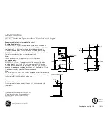
UH-200B
High Temperature with Built-in Booster
Fresh Water Final Rinse
UH-200
High Temperature
Fresh Water Final Rinse
UH-100B
High Temperature with Built-in Booster
Pumped Fresh Water Final Rinse
UL-100
Low Temperature
Chemical Sanitizing Rinse
Machine Serial No.
UH-100
High Temperature
Pumped Fresh Water Final Rinse
Champion
Model UH-200B Shown
2674 N. Service Road
Jordan Station, Ontario, Canada L0R 1S0
905/562-4195
Fax: 905/562-4618
PDF compression, OCR, web optimization using a watermarked evaluation copy of CVISION PDFCompressor