CHA TD 2.0
Page 9
Antenna Configurations
Using the supplied components, the CHA TD 2.0 can be deployed into a number of operationally useful
antenna configurations. The two primary antenna configurations described in this manual are the
Terminated Inverted “V” and
the Terminated Sloping Wire configurations.
Note: a floating Insulator
Ring is included on both Antenna Wires to enable other antenna configurations that require elevation of
the Antenna Wire somewhere along the wire
, such as an Inverted “L”
antenna.
Terminated Inverted
“V”
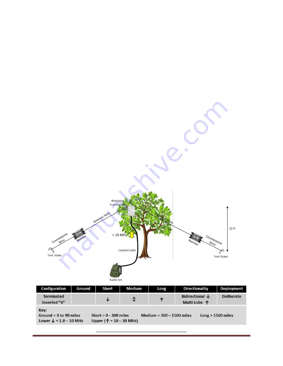
The CHA TD 2.0 Terminated Inverted
“V”
antenna, see figure (1), is a broadband medium to long range
HF antenna. It provides good medium range sky wave propagation on all frequencies and long-range sky
wave propagation above 10 MHz. It will also provide NVIS capability below 10 MHz.
Below 10 MHz, the antenna is bidirectional broadside to the antenna. Above 10 MHz, the pattern
contains multiple lobes. Bringing the ends of the antenna
towards each other to form a “V”, when seen
from above, converts the Inverted “V” into a Sloping “V” antenna.
This will cause the directivity of the
antenna to go from bidirectional to more unidirectional favoring
the opening of the “V”
on all but the
lowest frequencies. An opening angle of 90° will provide good overall performance, but opening angles
between 180° and 60° can be used. Larger opening angles increase performance on lower frequencies
and smaller angles on higher frequencies.
The Terminated Inverted “V” antenna, when raised to 25 feet, and with both the Antenna Wire and
Counterpoise Wire elevated, requires 163 feet of space. If needed, the Counterpoise Wire can be laid
on the ground, reducing the space required to around 110 feet.
Figure 1. Terminated Inverted V Configuration.


