CHA F-LOOP 2.0
Page 7
h.
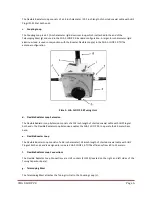
Tuning Knob
The Tuning Knob is located on the front of the Tuning Unit (a) and is used to adjust the resonant frequency of
the loop. The relative position of the tuning capacitor, which rotates around 2 ¾ revolutions is shown on the
front panel Tuning Quadrant Indicator. Left, or counter-clockwise, increases the resonant frequency of the
antenna. Right, or clockwise, decreases the resonant frequency of the antenna.
i.
Band Switch
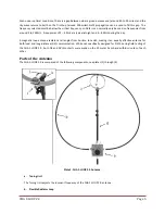
The Band Switch, see plate (3), is located on the top of the Tuning Unit (a). It has two positions, marked
“A”
and “B”.
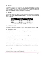
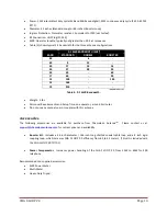
Table (2) shows the approximate transmit frequency range of the CHA F-LOOP 2.0 in the three
antenna configurations.
Antenna
Configuration
Frequency Range (MHz)
in A Position*
Frequency Range (MHz)
in B Position*
Standard
4.7
–
22.4
6.7
–
29.7
Double
2.8
–
10.2
5.0
–
11.9
Booster
4.0
–
17.9
5.4 - 23.1
*Range may vary
Table 2. CHA F-LOOP 2.0 and CHA F-LOOP TOTAL Frequency Ranges.
j.
Coupling Loop Attachment
The Coupling Loop Attachment is used to attach the Coupling Loop (c) to the top of the Telescoping Mast (g).
k.
Coupling Loop Adjustment
The Coupling Loop Adjustment is used to tighten the Coupling Loop Attachment (j).
l.
Loop Connection
The Loop Connection is a UHF socket located on the bottom of the Coupling Loop (c).
m.
Coaxial Cable Feedline
The Coaxial Cable Feedline
(not shown)
is a 12 foot length of RG-58 coaxial cable, with an RF isolator at the
antenna end, used to connect the CHA F-LOOP 2.0 Antenna to your radio.
n.
Aluminum Base Plate
The Aluminum Base Plate is on the bottom of the Tuning Unit (a). It is used to provide a stable base for
placing the CHA F-LOOP 2.0 on a flat surface, such as a table, or to mount the CHA F-LOOP 2.0 to a tripod or
other antenna mount with a 3/8” stud.
o.
Portable Bag
The Portable Bag
(not shown)
is a high quality military-style MOLLE bag used to store and transport the
components of the CHA F-LOOP 2.0, making it highly portable.


