CHA F-LOOP 2.0
Page 10
electromagnetic wave is maximum at the boundary between the ground and the space above, loop performance is
usually best when the loop is located near the
ground at a distance outside of the loop’s close
-in induction field
(just a loop diameter or two). The CHA F-LOOP 2.0 is not waterproof and must be installed in an area protected
from the weather. Do not use an antenna tuner or coupler with this antenna, as it may cause you to mistune the
antenna.
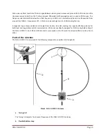
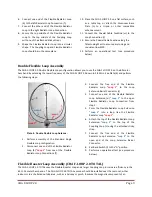
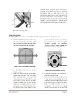
Perform the following steps to assemble the Flexible Booster Loop Antenna, see plates (2) and (3).
1.
Select a location to setup the CHA F-LOOP 2.0
TOTAL antenna. The location can be indoors or
in an outdoors area protected from the
weather. The location must facilitate
accessibility by the operator to the Tuning Knob
(h). The operator needs to be able to adjust the
Tuning Knob while listening to the receiver,
activating the transmitter, and observing the
SWR meter. If used indoors, the location should
also be reasonably away from switching power
supplies, Internet routers, and other sources of
electrical and electronic interference.
2.
Remove the CHA F-LOOP 2.0 TOTAL components
from the Portable Bag (o).
3.
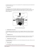
Attach the Telescoping Mast (g) to the Tuning
Unit (a) by screwing the bottom of the
Telescoping Mast onto the Telescoping Mast
Stud (q), located on the top of the Tuning Unit.
Tighten snuggly, by gripping the base of the
Telescoping Mast and turning clockwise. Do not
grip the mast tubing or use tools when
tightening.
4.
Attach the large 8 inch Coupling Loop (c) to the
Coupling Loop Attachment (j), located at the top
of the Telescoping Mast, by placing the
threaded hole in the Coupling Loop bracket over
the Coupling Loop Attachment stud and turning
the Coupling Loop Adjustment (k) knob until
snug. The UHF connector should be in front of
the Telescoping Mast and point down, as shown
in Plate (2).
5.
Fully extend the Telescoping Mast sections.
6.
Connect one end of the Flexible Booster Loop
(e) to the left Radiator Loop Connection (f).
7.
Connect the other end of the Flexible Booster
Loop to the right Radiator Loop Connection.
8.
Secure the top middle of the Flexible Booster
Loop to the top middle of the Coupling Loop
with one of the attached Sticky Straps.
9.
Shape the Flexible Booster Loop into a circular
shape. The Coupling Loop and Flexible Booster
Loop should be in the same plane.
10.
Place the CHA F-LOOP 2.0 on a flat surface, such
as a table top, or attach the Aluminum Base
Plate (n) to a tripod or other compatible
antenna mount.
11.
Connect the Coaxial Cable Feedline (m) to the
Loop Connection (l).
12.
Secure the Coaxial Cable Feedline along the
Telescoping Mast to ensure easy tuning and
consistent low SWR.
13.
Perform an operational test (see procedure
below).
Power Compensator Installation
The optional Power Compensator will increase the power handling capability of the CHA F-LOOP 2.0 to 60W
intermittent duty cycle (SSB telephony) and 25W continuous duty cycle (CW, AM, FM, RTTY, and SSB-based digital).
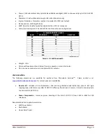
To install the Power Compensator, place the bracket of the Power Compensator (s) over the left Flexible Radiator
Loop Connection (f) and position the canister as shown in Plate (6).


