CHA F-LOOP 2.0
Page 11
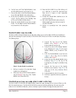
Plate 6. Power Compensator.
CAUTION: When using the Power Compensator,
exceeding the specified power limits or prolonged
transmission with an SWR above 2.0:1 will
permanently damage the internal components of
the Power Compensator. Also, dropping or rough
handling the Power Compensator will permanently
damage the internal components.
Damage caused
by these conditions is not covered by the warranty.
Loop Operation
The CHA F-LOOP 2.0 is very easy to use. Perform the following steps whenever you change frequency.
1.
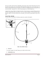
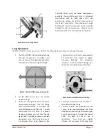
The CHA F-LOOP 2.0 is bidirectional favoring
the sides, see plate (7). If possible, point
one side toward the target signal and rotate
the antenna for maximum signal strength.
Plate 7. CHA F-LOOP Antenna Directivity.
2.
Set the Band Switch (i) to the desired
frequency range.
3.
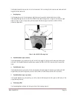
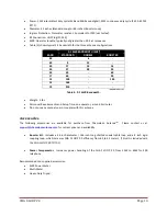
Adjust the Tuning Knob (h) for maximum
receive signal strength. Turn the Tuning
Knob counterclockwise to decrease the
resonant frequency, see Plate (8). You will
know when you are close to resonant
frequency because you will start hearing
signals and a marked increase in receiver
background noise. The Tuning Knob uses a
6:1 reduction drive which allows for fine
adjustment and will rotate approximately
2¾ revolutions from lowest to highest
frequency.
Although
the
mechanism
includes a clutch to prevent damage, you
should not force the knob past the stops.
Plate 8. CHA F-LOOP Antenna Tuning.
4.
Ensure your transmitter is set for no more
than 5 Watts during tuning.
5.
Transmit a carrier and gradually turn the
Tuning Knob counterclockwise and then
clockwise, around the highest receive signal
point found in step 3, to obtain the lowest
SWR. An SWR of 2.0:1 or less is
satisfactory. Your hand may slightly
influence the resonance of the loop while


