background image

28

CARE OF YOUR OPENER

LIMIT AND FORCE ADJUSTMENTS:

Weather conditions may cause
some minor changes in door
operation requiring some re-
adjustments, particularly during the
first year of operation.

Pages 23 and 24 refer to the limit
and force adjustments. Only a
screwdriver is required. Follow the 
instructions carefully.

Repeat the safety reverse test
(Adjustment Step 3, page 25) after
any adjustment of limits or force.

MAINTENANCE SCHEDULE

Once a Month

• Manually operate door. If it is unbalanced or binding,

call a trained door systems technician.

• Check to be sure door opens & closes fully. Adjust

limits and/or force if necessary. See pages 23 and 24.

• Repeat the safety reverse test. Make any necessary

adjustments. See Adjustment Step 3.

Once a Year

• Oil door rollers, bearings and hinges. The opener does

not require additional lubrication. Do not grease the
door tracks.

FORCE CONTROLS

1

3

9

7

5

1

3

9

7

5

KG

KG

LIMIT CONTROLS

THE REMOTE CONTROL BATTERY

The lithium battery should produce power for up to
5 years. 

NOTICE: To comply with FCC and or Industry Canada rules (IC), adjustment or modifications of
this receiver and/or transmitter are prohibited, except for changing the code setting or replacing
the battery. THERE ARE NO OTHER USER SERVICEABLE PARTS.
Tested to Comply with FCC Standards FOR HOME OR OFFICE USE. Operation is subject to the
following two conditions: (1) this device may not cause harmful interference, and (2) this device
must accept any interference received, including interference that may cause undesired operation.

To prevent possible SERIOUS INJURY or DEATH:
• NEVER allow small children near batteries.
• If battery is swallowed, immediately notify doctor.

WARNING

CAUTION

WARNING

WARNING

Battery 
positive 
side up (+)

To reduce risk of fire, explosion or chemical burn:
• Replace ONLY with 3V2032 coin batteries.
• Do NOT recharge, disassemble, heat above 100°C (212°F)

or incinerate.

WARNING

CAUTION

WARNING

WARNING

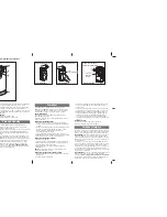
To replace battery, use the visor
clip or screwdriver blade to pry
open the case as shown. Insert
battery positive side up (+).

Dispose of old battery properly.

Replace the battery with only
3

V

2032 coin cell batteries.

Summary of Contents for Security+ 3130

Page 1: ... enclosed safety materials carefully Fasten the manual near the garage door after installation The door WILL NOT CLOSE unless the Protector System is connected and properly aligned Periodic checks of the opener are required to ensure safe operation The model number label is located on the front panel of your opener 3130 1 3 HP 3240 1 2 HP For Residential Use Only ...

Page 2: ...rt 30 Programming 31 32 To add or reprogram a hand held remote control 31 To erase all codes 31 3 Button remotes 31 To add reprogram or change a Keyless Entry PIN 32 Repair Parts 33 34 Rail assembly parts 33 Installation parts 33 Motor unit assembly parts 34 Accessories 35 Repair Parts and Service 36 Warranty 36 TABLE OF CONTENTS When you see these Safety Symbols and Signal Words on the following ...

Page 3: ...g your garage door Before you begin Disable locks Remove any ropes connected to garage door Complete the following test to make sure your garage door is balanced and is not sticking or binding 1 Lift the door about halfway as shown Release the door If balanced it should stay in place supported entirely by its springs 2 Raise and lower the door to see if there is any binding or sticking If your doo...

Page 4: ...een floor and bottom of door must not exceed 1 4 6 mm FINISHED CEILING Torsion Spring Access Door Motor Unit Wall mounted Door Control Rail Extension Spring OR Vertical Centerline of Garage Door SECTIONAL DOOR INSTALLATION Planning Identify the type and height of your garage door Survey your garage area to see if any of the conditions below apply to your installation Additional materials may be re...

Page 5: ...del 3240 Motor Unit with Light Lens Model 3130 Your garage door opener is packaged in two cartons which contain the motor unit and all parts illustrated below Accessories will depend on the model purchased If anything is missing carefully check the packing material Parts may be stuck in the foam Hardware for installation is also listed below Carton Inventory RAIL ASSEMBLY Coupling Sleeve 1 Hex Bol...

Page 6: ...nit as shown Slip the coupling over the rail sprocket Slide the rail through the motor unit bracket until the coupling fits securely over the motor unit sprocket Align the two bolt holes in the rail with those in the motor unit bracket Insert four 1 4 20x7 16 hex bolts Tighten securely with a 3 8 socket wrench Turn release arm down to disengage trolley Slide the trolley onto and along the bottom o...

Page 7: ...or 7 NEVER connect garage door opener to power source until instructed to do so 8 NEVER wear watches rings or loose clothing while installing or servicing opener They could be caught in garage door or opener mechanisms 9 Install wall mounted garage door control within sight of the garage door out of reach of children at minimum height of 5 feet 1 5 m away from ALL moving parts of the door 10 Place...

Page 8: ... the door NOTE If the total number of inches exceeds the height available in your garage use the maximum height possible or refer to page 9 for ceiling installation To prevent possible SERIOUS INJURY or DEATH Header bracket MUST be RIGIDLY fastened to structural support on header wall or ceiling otherwise garage door might not reverse when required DO NOT install header bracket over drywall Concre...

Page 9: ...UP CEILING MOUNT ONLY Wall Mounting Holes Optional Wall Mounting Holes The nail hole is for positioning only You must use lag screws to mount the header bracket UP CEILING MOUNT ONLY Door Spring Header Bracket 2x4 Structural Support Horizontal Line Vertical Centerline of Garage Door Vertical Centerline of Garage Door UP CEILING MOUNT ONLY Ceiling Mounting Holes The nail hole is for positioning onl...

Page 10: ...rely on a temporary support to allow the rail to clear the spring Position the rail bracket against the header bracket Align the bracket holes and join with a clevis pin as shown Insert a ring fastener to secure Header Bracket Rail Bracket Opener Carton or Temporary Support Header Wall Garage Door Rail Clevis Pin 5 16 x2 3 4 Ring Fastener Header Bracket Rail Bracket Rail Spacer Spacer Clevis Pin 5...

Page 11: ...ned to clip onto the track of sectional garage doors without additional hardware If it is necessary to mount the units on the wall the brackets must be securely fastened to a solid surface such as the wall framing Extension brackets see accessories are available if needed If installing in masonry construction add a piece of wood at each location to avoid drilling extra holes in masonry if repositi...

Page 12: ...e track It should lie flush with the lip hugging the back edge of the track as shown in Figure 1 If your door track will not support the bracket securely wall installation is recommended Wall installation Figures 2 3 Place the bracket against the wall with curved arms facing the door Be sure there is enough clearance for the sensor beam to be unobstructed If additional depth is needed an extension...

Page 13: ... each sensor Use wing nuts to fasten sensors to brackets with lenses pointing toward each other across the door Be sure the lens is not obstructed by a bracket extension Figure 5 Finger tighten the wing nuts Recommended Wire Routing 1 Using insulated staples run the wires from both sensors to the rail at the door header Figure 6 2 Run the wires through wire clips at the top of the rails NOTE If yo...

Page 14: ... is convenient for setting an ideal door to rail distance Raise the opener onto a stepladder You will need help at this point if the ladder is not tall enough Open the door all the way and place a 2x4 laid flat on the top section beneath the rail If the top section or panel hits the trolley when you raise the door pull down on the trolley release arm to disconnect inner and outer sections Slide th...

Page 15: ...ith the header bracket if the bracket is not centered above the door 7 Remove the 2x4 Operate the door manually If the door hits the rail raise the header bracket NOTE DO NOT connect power to opener at this time To avoid possible SERIOUS INJURY from a falling garage door opener fasten it SECURELY to structural supports of the garage Concrete anchors MUST be used if installing any brackets into mas...

Page 16: ...the rail See page 13 4 Insert all wires through the opening on top of motor unit above the terminal block on the back panel Figure 4 5 Strip 7 16 11 mm of insulation from each set of wires Insert door control wire into quick connect terminals by color white wire to white white red wire to red Separate white and white black wires sufficiently to connect to the opener quick connect terminals Twist l...

Page 17: ...through the hole in the release arm of the outer trolley Adjust rope length so the handle is 6 feet 1 83 m above the floor Secure with an overhand knot NOTE If it is necessary to cut the rope heat seal the cut end with a match or lighter to prevent unraveling To prevent possible SERIOUS INJURY or DEATH from a falling garage door If possible use emergency release handle to disengage trolley ONLY wh...

Page 18: ...RMANENT WIRING CONNECTION White Wire Black Wire WARNING CAUTION WARNING WARNING INSTALLATION STEP 11 Complete Safety Reversing Sensor Installation ALIGNING THE SAFETY REVERSING SENSORS Plug in the opener The indicator lights in both the sending and receiving eyes will glow steadily if wiring connections and alignment are correct The sending eye amber indicator light will glow regardless of alignme...

Page 19: ...the door panel support and the door bracket Drill 3 16 fastening holes Secure the door bracket using the two 1 4 14x5 8 self threading screws Figure 2A Alternately use two 5 16 bolts lock washers and nuts not provided Figure 2B Metal insulated or light weight factory reinforced doors Drill 3 16 fastening holes Secure the door bracket using the self threading screws Figure 3 Wood Doors Use top and ...

Page 20: ...UM STEEL DOORS WITH GLASS PANEL ETC NOT PROVIDED 20 ONE PIECE DOORS Please read and comply with the warnings and reinforcement instructions on the previous page They apply to one piece doors also Center the door bracket on the top of the door in line with the header bracket as shown Mark either the left and right or the top and bottom holes Metal Doors Drill 3 16 pilot holes and fasten the bracket...

Page 21: ...tion with a ring fastener Fasten curved section to the door bracket in the same way using the 5 16 x1 1 4 clevis pin Figure 2 Bring arm sections together Find two pairs of holes that line up and join sections Select holes as far apart as possible to increase door arm rigidity Figure 3 Hole alignment alternative If holes in curved arm are above holes in straight arm disconnect straight arm Cut abou...

Page 22: ...ust the limit further One full turn equals 2 5 cm of trolley travel Closed door adjustment decrease DOWN travel limit Turn the DOWN limit adjustment screw clockwise 4 complete turns Nuts 5 16 18 Lock Washers 5 16 Ring Fastener Straight Arm Bolts 5 16 18x7 8 Door Bracket Clevis Pin 5 16 x1 1 4 Curved Door Arm Press the Door Control push button The trolley will travel to the fully closed position Ma...

Page 23: ...as explained in Adjustment Step 2 If the door does not close completely Increase down travel Turn the down limit adjustment screw counterclockwise One turn equals 2 5 cm of travel If door still won t close completely and the trolley bumps into the pulley bracket page 4 try lengthening the door arm page 21 and decreasing the down limit If the opener reverses in fully closed position Decrease down t...

Page 24: ...clockwise Make small adjustments until the door completes a close cycle After each adjustment run the opener through a complete travel cycle Do not increase the force beyond the minimum amount required to close the door 2 Test the UP open force Grasp the door bottom when the door is about halfway through UP open travel The door should stop If the door is hard to hold or doesn t stop DECREASE UP op...

Page 25: ...he 1 1 2 3 8 cm board remove the obstruction and run the opener through 3 or 4 complete travel cycles to test adjustment IMPORTANT SAFETY CHECK Test the Safety Reverse System after Each adjustment of door arm length limits or force controls Any repair to or adjustment of the garage door including springs and hardware Any repair to or buckling of the garage floor Any repair to or adjustment of the ...

Page 26: ...ion Door Control is activated Bulb size is A19 Bulb power is 100 watts maximum Security light feature Lights will also turn on when someone walks through the open garage door With a Multi Function Door Control this feature may be turned off as follows With the opener lights off press and hold the light button for 10 seconds until the light goes on then off again To restore this feature start with ...

Page 27: ...it on and then activate the opener the light will remain on for 4 1 2 minutes Press again to turn it off sooner The 4 1 2 minute interval can be changed to 1 1 2 2 1 2 or 3 1 2 minutes as follows Press and hold the Lock button until the light blinks about 10 seconds A single blink indicates that the timer is reset to 1 1 2 minutes Repeat the procedure and the light will blink twice resetting the t...

Page 28: ...battery should produce power for up to 5 years NOTICE To comply with FCC and or Industry Canada rules IC adjustment or modifications of this receiver and or transmitter are prohibited except for changing the code setting or replacing the battery THERE ARE NO OTHER USER SERVICEABLE PARTS Tested to Comply with FCC Standards FOR HOME OR OFFICE USE Operation is subject to the following two conditions ...

Page 29: ...nts to force or travel limits The need for occasional adjustment for the force and limit settings is normal Weather conditions in particular can affect door travel Manually check door for balance or any binding problems Refer to Adjustment Step 2 Adjust the Force 4 My door reverses for no apparent reason after fully closing and touching the floor Repeat safety reverse test after adjustments to for...

Page 30: ...s dim or flashing Realign receiving eye sensor clean lens and secure brackets Verify door track is firmly secured to wall and does not move Symptom Motor has over heated the motor unit does not operate RPM Sensor Short travel 6 8 15 20 cm Unplug unit to reset Try to operate motor unit check diagnostic code If it is still flashing 5 times and motor unit moves 6 8 15 20 cm replace RPM sensor If moto...

Page 31: ...the learn button on the motor unit The learn indicator light will glow steadily for 30 seconds 2 Within 30 seconds press and hold the button on the hand held remote that you wish to operate your garage door 3 Release the button when the motor unit lights blink It has learned the code If light bulbs are not installed two clicks will be heard To Add and Reprogram an Additional Hand held Remote Contr...

Page 32: ... after it has expired To set a temporary PIN 1 Press the four buttons for your personal entry PIN not the last temporary PIN then press and hold the button The opener light will blink three times Release the button 2 Press the temporary 4 digit PIN you have chosen then press Enter The opener light will blink four times 3 To set the number of hours this temporary PIN will work press the number of h...

Page 33: ...cket w clevis pin fastener 11 41A5034 Safety sensor kit receiving and sending eyes with 3 9 m 2 conductor bell wire attached 12 41A5266 1 Safety sensor bracket 13 41B4494 1 2 Conductor bell wire white white red 14 178B35 Curved door arm section NOT SHOWN 41A4675 7 Installation hardware bag see page 5 114A3331 Owner s manual 114A3331SP Owner s manual Spanish Installation Parts REPAIR PARTS Rail Ass...

Page 34: ...a 20B21 1 Drive belt 7 41C4672 Screw drive RPM kit KEY PART NO NO DESCRIPTION 8 41A4837 1 Worm gear and retainer 9 41A6335 Low voltage wire harness 9a 41A6334 High voltage wire harness 10 41AS050R1 Receiver logic board 3130 41AS050R2 Receiver logic board 3240 11 41A5525 57 Cover Model 3130 41A5525 53 Model 3240 12 41C22 1 Drive coupling hub 13 175B88 Light socket 14 108D79 Light lens DN UP Brown W...

Page 35: ...three controls into one wall control panel for a neat compact appearance Enhanced functions include Lock Feature to lock out outside radio signals while you are away from home and turn opener lights on or off from the control panel 377LM Garage Door Monitor Security for the largest door of your home Tells you if your garage door is open or closed Monitors up to 4 garage doors by adding additional ...

Page 36: ...pair which upon receipt by Seller are confirmed to be defective and covered by this limited warranty will be repaired or replaced at Seller s sole option at no cost to you and returned pre paid Defective parts will be repaired or replaced with new or factory rebuilt parts at Seller s sole option ALL IMPLIED WARRANTIES FOR THE PRODUCT INCLUDING BUT NOT LIMITED TO ANY IMPLIED WARRANTIES OF MERCHANTA...

Reviews: